C++ Blynk (Legacy) - Code Examples for Basic Tasks

#6 Matrix of LARGE Randomly Flashing & Coloured Virtual RGB “Super LEDs” (AKA Buttons)

I don’t know why I didn’t do this one sooner… less energy and at about 80% less “LEDs” to flash, it should be theoretically faster… well… it costs less energy at least :stuck_out_tongue: (3200 units of energy)

Challenge Question for the Developers… why is it seem faster to change the colour properties on 71 LEDs compared to 16 Buttons?

Even the QR looks more complex… but then Buttons do have more settings then an LED :stuck_out_tongue:
image

#include <ESP8266WiFi.h>
#include <BlynkSimpleEsp8266.h>

#include <ESP8266mDNS.h>  // For OTA
#include <WiFiUdp.h>  // For OTA
#include <ArduinoOTA.h>  // For OTA

#define BLYNK_NO_BUILTIN  // Disable built-in analog & digital pin operations
#define BLYNK_MAX_READBYTES 1024
#define BLYNK_MSG_LIMIT 0
#define BLYNK_HEARTBEAT 60

BlynkTimer timer;

char auth[] = "xxxxxxxxxx";
char ssid[] = "xxxxxxxxxx";
char pass[] = "xxxxxxxxxx";
//char server[] = "xxx.xxx.xxx.xxx";  // IP for your Local Server
char server[] = "blynk-cloud.com";  // URL for Blynk Cloud Server
int port = 8080;
String HEXstring;
int randLED;
int randIntensity;
int rrr, ggg, bbb;
int RandomTimer;


void setup() {
  WiFi.begin(ssid, pass); 
  // Preset for use on a Local Server... adjust as required for Cloud Server
  Blynk.config(auth, server, port);
  Blynk.connect();
  for (int i = 0; i <= 16; i++) {
    Blynk.virtualWrite(i, 1);  // Set Button ON
    Blynk.setProperty(i, "label", " ");  // Set Button Label to blank
    Blynk.setProperty(i, "color", "#000000");  // Set Button colour to black
  }
  RandomTimer = timer.setInterval(30L, RGBMatrix);
  ArduinoOTA.setHostname("ESP8266 BIG vRGB Matrix");  // For OTA
  ArduinoOTA.begin();  // For OTA
}


void loop() {
  Blynk.run();
  timer.run();
  ArduinoOTA.handle();
}


void RGBMatrix() {
  randLED = random(17);
  rrr = random(256);
  ggg = random(256);
  bbb = random(256);
  String strRED = String(rrr, HEX);  // Convert RED DEC to HEX.
  if (rrr < 16) {
    strRED = String("0" + strRED);  // Buffer with 0 if required.
  }  // END if
  String strGRN = String(ggg, HEX);  // Convert GREEN DEC to HEX.
  if (ggg < 16)  {
    strGRN = String("0" + strGRN);  // Buffer with 0 if required.
  }  // END if
  String strBLU = String(bbb, HEX);  // Convert BLUE DEC to HEX.
  if (bbb < 16)  {
    strBLU = String("0" + strBLU);  // Buffer with 0 if required.
  }  // END if
  String HEXstring = String("#" + strRED + strGRN + strBLU);  // Combine HEX fragments.
  Blynk.setProperty(randLED, "color", HEXstring);  // Set LED Label to HEX colour
}
5 Likes

#7 !! NodeJS !! - Pan & Tilt Servo control with Joystick for Raspberry Pi using NodeJS

And now for something different… here is some simple javascript code for using the joystick widget with a couple servos on an RPi for use with a pan and tilt base. More NodeJS stuff here :wink:

Hook up your two servos with 5v, GND and GPIO pins 22 & 23 .
I recommend a dedicated 5v supply and remember to share the GND with the RPi.

Joystick Widget set for vPin 22 & 23 (to match the GPIO just for hookup convenience, they can be any other vPins) and whatever range settings work best for your servos.

const Gpio = require('pigpio').Gpio;
const PAN_PORT = 22;
const TILT_PORT = 23;
const pan = new Gpio(PAN_PORT, {mode: Gpio.OUTPUT});
const tilt = new Gpio(TILT_PORT, {mode: Gpio.OUTPUT});
const Blynk = require('blynk-library');  // Links variable 'Blynk' to the Blynk Library

const AUTH = 'xxxxxxxxxx';

// ----- Use this with Cloud Server.
//  var blynk = new Blynk.Blynk(AUTH, options = { connector : new Blynk.TcpClient()  });

// ----- Use this with Local Server.
var blynk = new Blynk.Blynk(AUTH, options = { connector : new Blynk.TcpClient( options = { addr: "xxx.xxx.xxx.xxx", port: 8080 } ) });

var JoyX = new blynk.VirtualPin(22);  // Setup Joystick X on V22
var JoyY = new blynk.VirtualPin(23);  // Setup Joystick Y on V23

JoyX.on('write', function(panValue) {  // Watches for Joystick X
  pan.servoWrite(panValue);  // Set Servo to value
});

JoyY.on('write', function(tiltValue) {  // Watches for Joystick y
  tilt.servoWrite(tiltValue);  // Set Servo to value
});
7 Likes

#8 Simple AC Power Monitor (Using ACS712)

This is something I have running on my workbench… simply monitoring the power used by my computer system. So the current adjustments visible on the graph are the difference between my monitors being on or off.

The shading is normal, but I am also using the gradient colour so that it goes from green at its lowest to red at its highest.

image

I have mounted my sensor in an old power tap / spike regulator box…
Not sure I would trust it to the full 15A :zap: :fire::fire:

And yes, it is presently running on a lowly Arduino UNO using the USB Link :stuck_out_tongue_winking_eye:

http://help.blynk.cc/how-to-connect-different-hardware-with-blynk/arduino/usb-serial

I “upgraded” my UNO that runs this AC Current Monitor. Since the UNO only needed one Analog port for the job… and that was all that is left over with these old LCD shields… I added the shield (no not including the merged-into-Blynk Paint code here :wink: ) but eventually I will instead use the display for actual AC current data… maybe even as a clock :thinking:

#include <BlynkSimpleStream.h>  // For USB Link
//#include <ESP8266WiFi.h>  // For WiFi with standalone ESP8266
//#include <BlynkSimpleEsp8266.h>  // For WiFi with ESP8266 as shield for Arduino

char auth[] = "xxxxxxxxxx";
// char ssid[] = "xxxxxxxxxx";  // For WiFi
// char pass[] = "xxxxxxxxxx";  // For WiFi
// char server[] = "10.10.3.13";  // For WiFi - IP for your Local Server
// char server[] = "blynk-cloud.com";  // For WiFi - IP for your Local Server

const int sensorIn = A0;
int mVperAmp = 100; // use 100 for 20A Module and 66 for 30A Module
double Voltage = 0;
double VRMS = 0;
double AmpsRMS = 0;

BlynkTimer timer;

WidgetTerminal terminal(V1);

void setup() {
  Serial.begin(9600);  // USB Link
  Blynk.begin(Serial, auth);  // For USB Link
  // WiFi.begin(ssid, pass);  // For WiFi
  // Blynk.config(auth, server, port);  // For WiFi
  // Blynk.connect();  // For WiFi
  timer.setInterval(2000L, SensorRead);
}


void loop() {
  Blynk.run();
  timer.run();
}


void SensorRead() {
  Voltage = getVPP();
  VRMS = (Voltage / 2.0) * 0.707;
  AmpsRMS = (VRMS * 1000) / mVperAmp;
  Blynk.virtualWrite(V0, 0.9 * AmpsRMS * 110);  // To Gauge Widget @ .9pf and 110vac
  terminal.print(AmpsRMS);  // To Terminal Widget
  terminal.print(" Amps - ");
  terminal.flush();
}


float getVPP() {
  float result;
  int readValue;  //value read from the sensor
  int maxValue = 0;  // store max value here
  int minValue = 1023;  // store min value here
  uint32_t start_time = millis();
  while ((millis() - start_time) < 1500) {  // sample for 1 Sec
    readValue = analogRead(sensorIn);  // see if you have a new maxValue
    if (readValue > maxValue) {
      maxValue = readValue;  // record the maximum sensor value
    }
    if (readValue < minValue) {
      minValue = readValue;  // record the minimum sensor value
    }
  }
  // Subtract min from max
  result = ((maxValue - minValue) * 5.0) / 1023.0;
  return result;
}


void ac_read() {
  int rVal = 0;
  int sampleDuration = 100;  // 100ms
  int sampleCount = 0;
  unsigned long rSquaredSum = 0;
  int rZero = 511;   // For illustrative purposes only - should be measured to calibrate sensor.
  uint32_t startTime = millis();  // take samples for 100ms
  while ((millis() - startTime) < sampleDuration) {
    rVal = analogRead(A0) - rZero;
    rSquaredSum += rVal * rVal;
    sampleCount++;
  }
  double voltRMS = 5.0 * sqrt(rSquaredSum / sampleCount) / 1024.0;
  // x 1000 to convert volts to millivolts
  // divide by the number of millivolts per amp to determine amps measured
  // the 20A module 100 mv/A (so in this case ampsRMS = 10 * voltRMS
  double ampsRMS = voltRMS * 10.0;
}
7 Likes

#9 Basic “Keeps running without WiFi or Blynk Server connection, but reconnects as soon as they are available” sketch

Simply does what the title says… Flashes the built in LED and sends UpTime data to both App and Serial monitor to show operation either way. Also has a lot of serial print commands to show general operation for troubleshooting… Remove them when you are comfortable that everything works for you.

#define BLYNK_PRINT Serial // This prints to Serial Monitor
#include <ESP8266WiFi.h>
#include <BlynkSimpleEsp8266.h>

#include <ESP8266mDNS.h>  // For OTA
#include <WiFiUdp.h>  // For OTA
#include <ArduinoOTA.h>  // For OTA

char auth[] = "xxxxxxxxxx";
char ssid[] = "xxxxxxxxxx";
char pass[] = "xxxxxxxxxx";
//char server[] = "xxx.xxx.xxx.xxx";  // IP for Local Cloud Server
char server[] = "blynk-cloud.com";  // URL for Blynk Cloud Server
int port = 8080;

int DeviceLED = 2;
int ReCnctFlag;  // Reconnection Flag
int ReCnctCount = 0;  // Reconnection counter

BlynkTimer timer;


void setup() {
  Serial.begin(115200);
  pinMode(2, OUTPUT);

  WiFi.begin(ssid, pass);  // Non-blocking if no WiFi available
  Blynk.config(auth, server, port);
  Blynk.connect();

  timer.setInterval(1000L, UpTime);

  ArduinoOTA.setHostname("Loss of connection test");  // For OTA
  ArduinoOTA.begin();  // For OTA
}


BLYNK_CONNECTED() {
  Serial.println("Cconnected");
  ReCnctCount = 0;
}


void UpTime() {
  Blynk.virtualWrite(V0, millis() / 1000);  // Send UpTime seconds to App
  Serial.print("UpTime: ");
  Serial.println(millis() / 1000);  // Send UpTime seconds to Serial
  digitalWrite(DeviceLED, !digitalRead(DeviceLED));  // Blink onboard LED
}


void loop() {
  timer.run();
  ArduinoOTA.handle();  // For OTA

  if (Blynk.connected()) {  // If connected run as normal
    Blynk.run();
  } else if (ReCnctFlag == 0) {  // If NOT connected and not already trying to reconnect, set timer to try to reconnect in 30 seconds
    ReCnctFlag = 1;  // Set reconnection Flag
    Serial.println("Starting reconnection timer in 30 seconds...");
    timer.setTimeout(30000L, []() {  // Lambda Reconnection Timer Function
      ReCnctFlag = 0;  // Reset reconnection Flag
      ReCnctCount++;  // Increment reconnection Counter
      Serial.print("Attempting reconnection #");
      Serial.println(ReCnctCount);
      Blynk.connect();  // Try to reconnect to the server
    });  // END Timer Function
  }
}

NOTE: And here is an enhanced version made by another Blynk Forum member :smiley:

21 Likes

#10 - Basic sketch layout The terms, whys and hows explained… perhaps…

OK, this is just a simple layout of a typical sketch… wherein I will define things like pre-setup, setup(), main loops, functions, etc… these may not be canon in terminology, but it works for me… perhaps for others as well :stuck_out_tongue_winking_eye:

//  This area is what I call pre-setup.  Here you load your libraries, define variables, setup special pin references... basically this is NOT a loop that runs any real code, but some special functions can be placed up here.


// This is the run once per boot loop... here you begin() routines, sensors, etc, initialize timers, set pinMode() etc.
void setup() 
{
  // put your setup code here, to run once:
}


 // Typical Arduino Function... you put specific routines in here and call it from a timer or function call - e.g  myFunction();
void MyFunction()
{ 
  // Generic code functions & stuff here
  // typically called from other functions as needed.
}


// This is called a Blynk Function... basically runs like an Arduino Function, but using App triggered widgets, linked to the same vPin to "call' it whenever a Widget, set to PUSH changes state.
BLYNK_WRITE(vPin) 
{  
  //  Blynk function stuff here
  //  called whenever the associated widget or vPin changes state
}


// this is the loop that constantly runs as fast as it can... with Blynk we try to keep it as clear as possible.
void loop() 
{
  // continuously looping stuff here... like Blynk.run(); and timer.run();
}
8 Likes

#11 - The simple, but mystifyingly complex, Bridge

The Bridge is meant to allow totally separate projects to share data, and/or control things between themselves. You can also have just one project with multiple devices, but have any of the 1st device’s Blynk functions triggered directly by Bridge code in the 2nd device… bypassing the App.

As long as the Auth tokens were generated on the same server, then this can even share between different accounts… I think? :thinking:

Basically, Blynk Bridge is a way of emulating a receiving device’s App input, triggering a Physical Pin or Virtual Pin (using a BLYNK_WRITE() function), but the triggering action came from another transmitting device’s code, not the App… say all that five times fast :stuck_out_tongue:

OK, here is a simple bidirectional Bridge network between two identical sketches/devices… (does not have to be identical, but this is for demonstration :stuck_out_tongue_winking_eye: )

This example has two projects/devices. On each project you can toggle the ‘Local’ project’s device’s LED with Button V0 or the ‘remote’ project’s device’s LED with Button V1… and visa versa.

NOTE for each device’s sketch, comment out the Upper OR Lower AUTH and Bridge tokens, depending on which project you are flashing this sketch to.

For example… use these top settings for Project/device A, and the bottom ones for Project/device B

image

For the App projects, simply add in two buttons, Local LED (V0) and Remote LED (V1) for each project.

*** Don’t forget to add in the Bridge Widget to each project that sends data to another

Also, when using Built In LED’s they are usually triggered LOW, so to make that make visual sense, simply reverse each Button’s settings as such…

#include <ESP8266WiFi.h>
#include <BlynkSimpleEsp8266.h>

char auth[] = "aaaaaaaaaa";  // Token for Device A
//char auth[] = "bbbbbbbbbb";  // Token for Device B

char ssid[] = "xxxxxxxxxx";
char pass[] = "xxxxxxxxxx";
//char server[] = "xxx.xxx.xxx.xxx";  // IP for your Local Server
char server[] = "blynk-cloud.com";  // URL for Blynk Cloud Server
int port = 8080;
#define DeviceLED 2 // Built in LED for Wemos or NodeMCU v3, Or 16 for NodeMCU v1

WidgetBridge bridge1(V127); //  Initiating Bridge Widget on V127 (this is just as holding pin for the bridge, can be any unused vPin and each bridge needs its own)


void setup() {
  pinMode(DeviceLED, OUTPUT);
  WiFi.begin(ssid, pass);
  Blynk.config(auth, server, port);
  Blynk.connect();
}


BLYNK_CONNECTED() {
  bridge1.setAuthToken("bbbbbbbbbb"); // Token of the Device B
  //bridge1.setAuthToken("aaaaaaaaaa"); // Token of the Device A
}


BLYNK_WRITE(V0) { // Local LED
  digitalWrite(DeviceLED, param.asInt()); // take the state of the Button and send it to the Local LED
}


BLYNK_WRITE(V1) { // Remote LED
  bridge1.virtualWrite(V0, param.asInt()); // take the state of the Button and send it to the Remote LED
}

This concept is completely upgradable to anything else you want to control via Bridge.


NOTE: When using Blynk Functions on the receiving side, you MUST have a widget for the receiving vPin in that devices project… just use the same vPin for both the Blynk Function and the Widget’s Blynk.virtualWrite() command…

Sending Project…

void MEGAupdate() { //  Timed Function
  bridge1.virtualWrite(V43, t);  // Solar DHT22 Temperature to receiving project
  bridge1.virtualWrite(V44, h);  // Solar DHT22 Humidity to receiving project
  bridge1.virtualWrite(V47, current_mA);  // Solar Panel Current to receiving project
  bridge1.virtualWrite(V48, busvoltage);  // Solar Battery Voltage to receiving project
}

Receiving Project…

BLYNK_WRITE(V43) { // Solar DHT22 Temperature from sending project
  Blynk.virtualWrite(V43, param.asFloat());
}

BLYNK_WRITE(V44) { // Solar DHT22 Humidity from sending project
  Blynk.virtualWrite(V44, param.asFloat());
}

BLYNK_WRITE(V47) { // Solar Panel Current from sending project
  Blynk.virtualWrite(V47, param.asFloat());
}

BLYNK_WRITE(V48) { // Solar Battery Voltage from sending project
  Blynk.virtualWrite(V48, param.asFloat());
}

NOTE: When initiating the bridges, you can use any name and available (unused) vPin on the “transmitter” project’s side… but each separately defined bridge (AKA for seperate MCUs) does need a different vPin.

These "holding’ vPins are NOT the same as whatever vPins you are trying to control on the receiving side… so there is NO need to make them the same unless you really like it that way…

For example…

WidgetBridge MyNodeMCU(V125); //  Initiating Bridge Widget on V125 (this is just as holding pin for the bridge, can be any unused vPin and each bridge needs its own)

WidgetBridge MyWemos(V126); //  Initiating Bridge Widget on V126 (this is just as holding pin for the bridge, can be any unused vPin and each bridge needs its own)

WidgetBridge MyUNO(V127); //  Initiating Bridge Widget on V127 (this is just as holding pin for the bridge, can be any unused vPin and each bridge needs its own)
BLYNK_CONNECTED() {
  MyNodeMCU.setAuthToken("AuthToken of NodeMCU"); // Token of the hardware A
  MyWemos.setAuthToken("AuthToken of Wemos"); // Token of the hardware B
  MyUNO.setAuthToken("AuthToken of UNO"); // Token of the hardware C
}
BLYNK_WRITE(V0) {
  MyNodeMCU.virtualWrite(V3, param.asInt()); // take the state of this transmitting MCU's virtual V0 button and send it to the receiving MCU's V3 vPin
}

BLYNK_WRITE(V1) { 
  MyWemos.virtualWrite(V8, param.asInt()); // take the state of this transmitting MCU's virtual button on V1 and send it to the receiving MCU's V8 vPin
}

BLYNK_WRITE(V2) { 
  MyUNO.digitalWrite(13, param.asInt()); // take the state of this transmitting MCU's virtual button on V2 and send it to the receiving MCU's GPIO13
}
9 Likes

#12 - Timers simplified… perhaps… :slight_smile:

Some have a difficult time understanding timers… and since this is a fundamental building block of Blynk… I buried this reference in the middle of this entire topic :innocent: Well anyhow…

This is a “real world” timer example where i am using two timers to alternately turn ON and OFF an LED… yes, there are many ways to do this, but this example is all about timers.

  • The first timer will run it’s assigned function 500ms (1/2 second) after bootup, and every 500ms after.

  • The second timer will run it’s assigned function 1000ms (1 second) after bootup and every 1000ms after

This in effect will cause the LED to blink ON and OFF every 1/2 second.

In this case I used both timers for the same LED action, but normally you would run one timer to run a function that flashes the LED on and off (we will look a various ways to do that later), while the 2nd would run a function that gets sensor data and sends it to the App… and so on.

I did it this way to show that you can have multiple timers running (up to 16 per instance)… in this case the instance is called timer… but could have easily been called blinker, flasher or fred… just be sure to declare the timer name and use it accordingly in the setup… E.g.

BlynkTimer fred;

fred.setInterval(500L, blinkMyLEDon); 

But for this example, lets stick with the name timer :wink:

NOTE Because both these timers initialize at the same time (at boot) it is important to stagger timers (more info below) enough to allow their associated functions to complete their task… otherwise you can get some interesting stuttering and lockups in your sketch.

#include <ESP8266WiFi.h>
#include <BlynkSimpleEsp8266.h>

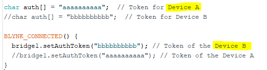
char auth[] = "xxxxxxxxxx";  // Token for Device A
char ssid[] = "xxxxxxxxxx";
char pass[] = "xxxxxxxxxx";
//char server[] = "xxx.xxx.xxx.xxx";  // IP for your Local Server
char server[] = "blynk-cloud.com";  // URL for Blynk Cloud Server
int port = 8080;

#define DeviceLED 2 // Built in LED for Wemos or NodeMCU v3, Or 16 for NodeMCU v1


void setup() {
  pinMode(DeviceLED, OUTPUT);
  WiFi.begin(ssid, pass);
  Blynk.config(auth, server, port);
  Blynk.connect();

  timer.setInterval(500L, blinkMyLEDon);  // This will call the Arduino Function 'void blinkMyLEDon()' every 500ms (1/2 second)

  timer.setInterval(1000L, blinkMyLEDoff);  // This will call the Arduino Function 'void blinkMyLEDoff()' every 1000ms (1 second)
}


void blinkMyLEDon() {
  digitalWrite(DeviceLED, LOW); // Turn ON built in LED (triggered LOW)
}

void blinkMyLEDoff() {
  digitalWrite(DeviceLED, HIGH); // Turn OFF built in LED (triggered LOW)
}


void loop() {
  Blynk.run();
  timer.run(); // This keeps checking the timers to see if then need to be processed
}

  • Latch & indicator Here is another example with the timers that, with a press of a button, you can trigger a relay on for 10 seconds, while flashing an indicator LED the entire time.

NOTE: This “time” :stuck_out_tongue_winking_eye: the timers are NOT initialized in the void setup() since they do not need to run all the time from boot. These timers setTimer() and setTimout() just run when called, and for as long as told to, and that is it.

#include <ESP8266WiFi.h>
#include <BlynkSimpleEsp8266.h>

char auth[] = "xxxxxxxxxx";
char ssid[] = "xxxxxxxxxx";
char pass[] = "xxxxxxxxxx";
//char server[] = "xxx.xxx.xxx.xxx";  // IP for your Local Server
char server[] = "blynk-cloud.com";  // URL for Blynk Cloud Server
int port = 8080;
int Latch;
int Flag;
#define DeviceLED 2 // Built in LED for Wemos or NodeMCU v3, Or 16 for NodeMCU v1
#define LatchRelay 12 //  GPIO12 or D6

BlynkTimer timer;


void setup() {
  pinMode(DeviceLED, OUTPUT);
  pinMode(LatchRelay, OUTPUT);
  WiFi.begin(ssid, pass);
  Blynk.config(auth, server, port);
  Blynk.connect();
}


//===== LATCH(Relay) & LED PULSE - BLYNK Functions =====
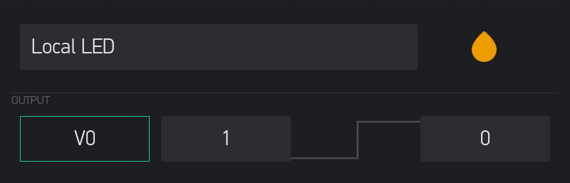
BLYNK_WRITE(V0)  // Virtual button on V0 to activate Relay_LED pulses
{
  //Serial.println("Latch LED");
  Latch = param.asInt();
  if (Latch == 1 && Flag == 0) {
    Flag = 1;  // Keeps from allowing button press more then once while relay activated
    digitalWrite(LatchRelay, HIGH); // Activate Relay
    timer.setTimer(1000L, blinkMyLEDon, 10);  // Pulse LED routine (LedON/LedOFF) 10 times
    timer.setTimeout(10000L, RelayOFF);  // Deactivare Relay after 10 seconds
  }  // END if
}  // END Blynk Function

void RelayOFF() {
  digitalWrite(LatchRelay, LOW);
  Flag = 0;  // reset flag after relay disables
}  // END Function

void blinkMyLEDon() {
  digitalWrite(DeviceLED, LOW); // Turn ON built in LED (triggered LOW)
  timer.setTimeout(500L, blinkMyLEDoff);  // Run LED OFF routine once in 1/2 second
}  // END Function

void blinkMyLEDoff() {
  digitalWrite(DeviceLED, HIGH); // Turn OFF built in LED (triggered LOW)
}  // END Function


void loop() {
  Blynk.run();
  timer.run(); // This keeps checking the timers to see if then need to be processed
}

Staggering Timers:

Stagger the timers so that each one starts a little later then the prior one… but also giving its function time to complete.

Also try not to have timers match on alternating cycles… like a timer every 1 second another every 5 seconds and a third every 60 seconds… as some and/or all will eventually try to run at the same time every few cycles.

For example… eight timed functions, running all timers within 200 ms from start to finish, and repeating the process every second… assuming 20 ms is enough time for each function to complete its task before the next one runs…

  timer.setInterval(1000L, myFunction1);
  timer.setInterval(1020L, myFunction2);
  timer.setInterval(1040L, myFunction3);
  timer.setInterval(1080L, myFunction4);
  timer.setInterval(1100L, myFunction5);
  timer.setInterval(1120L, myFunction6);
  timer.setInterval(1140L, myFunction7);
  timer.setInterval(1160L, myFunction8);

NOTE: While each timer starts counting at the same time (as is the way it should be) , they run each of their respective first functions 20ms later then it’s predecessor, and thus each subsequent function call continues to run at a different time hence forth. any eventual overlap (because I am using evenly divisible timers in this example) is few and far between. I have actual projects running like this without issues.

You can test if 20ms is enough by having print statements at the beginning and end of each function… then if one function starts before the other ends, you will see the print statements out of order. Be aware that the print statements themselves will take a small amount of time to process.

If the actual time between individual timers is more important then having them all start at the same time (AKA they all MUST be one second intervals, but still not running at the same time), you can also stagger timers this way…

  timer.setInterval(1000L, myFunction1);
  delay(20);
  timer.setInterval(1000L, myFunction2);
  delay(20);
  timer.setInterval(1000L, myFunction3);
  delay(20);
  timer.setInterval(1000L, myFunction4);
  delay(20);
  timer.setInterval(1000L, myFunction5);
  delay(20);
  timer.setInterval(1000L, myFunction6);
  delay(20);
  timer.setInterval(1000L, myFunction7);
  delay(20);
  timer.setInterval(1000L, myFunction8);
8 Likes

#13 - The All-in-One Timer Function (AKA Lambda Function) - No, I don’t entirely understand it… but it works :stuck_out_tongue_winking_eye:

I like this for it’s relative simplicity… no separate function to call (or write in the code) I just copy/paste my most used into my new sketches…


in your pre-setup…

BlynkTimer timer;

And in your void setup()

  // Timed Lambda Function - UpTime counter
  timer.setInterval(1000L, []() {  // Run every second
    Blynk.virtualWrite(V0, millis() / 60000);  // Display the UpTime in Minutes
  });  // END Timer Function

  • Lambda routine for the DHT sensor. With the Lambda, you you can combine commands and even add in some logic, just like normal… just more compact. Here is a simple example…
    In your pre-setup…
#include <DHT.h>  // For DHT22
#define DHTPIN 0  // GPIO0(D3) on Wemos D1 Mini
#define DHTTYPE DHT22
DHT dht(DHTPIN, DHTTYPE);
float h, t;

And in your void setup()

  // Timed Lambda Function - DHT22 Temp & Humidity sensor
  timer.setInterval(300000L, []() {  // Run every 5 minutes
    h = dht.readHumidity();
    t = dht.readTemperature(); // or dht.readTemperature(true) for Fahrenheit
    if (isnan(h) || isnan(t)) {  // Check if any reads failed and try once more this cycle.
      delay(250);  // short delay before recheck
      h = dht.readHumidity();
      t = dht.readTemperature(); // or dht.readTemperature(true) for Fahrenheit
    }
    Blynk.virtualWrite(V1, h);  // Display Humidity
    Blynk.virtualWrite(V2, t);  // Display Temperature
  });  // END Timer Function
5 Likes

#14 - ESP32 - Alternate way to control PWM pins for Servos and/or LEDs

At the time of this posting, the ESP32 Arduino Core does not support the handy analogWrite() command. So how do we do the PWM dodo we want to do?

Well, a little G :eyes: gling later and I found a few different websites that describe in more detail then I will get into here. How profoundly customisable the ESP32 GPIO pins are :smiley:

First you need this library…

And here is just a couple of sites with usage examples…

Basicly the GPIO pins can be linked to 16 independent channels, with configurable duty cycles and wave periods. The accuracy of the duty cycle can be configured up to 16 bits of resolution.

I am using 50Hz and 16-bits for the Servo control. for my servo 2000-8000 was a good range in the settings, without pushing the limits of the servo.

And for the RGB LED I am using 5000Hz but only 8-bits to give the range of 0-255 in the settings

For those that like to visually see results right darn now!!.. here is a small project that you can use… and even if you don’t have a servo motor or a 4 lead RGB LED, you will see the results on the App (OK a Gauge Widget is a poor substitute for a Servo :blush: but the HEX data that shows the corresponding colour is useful)
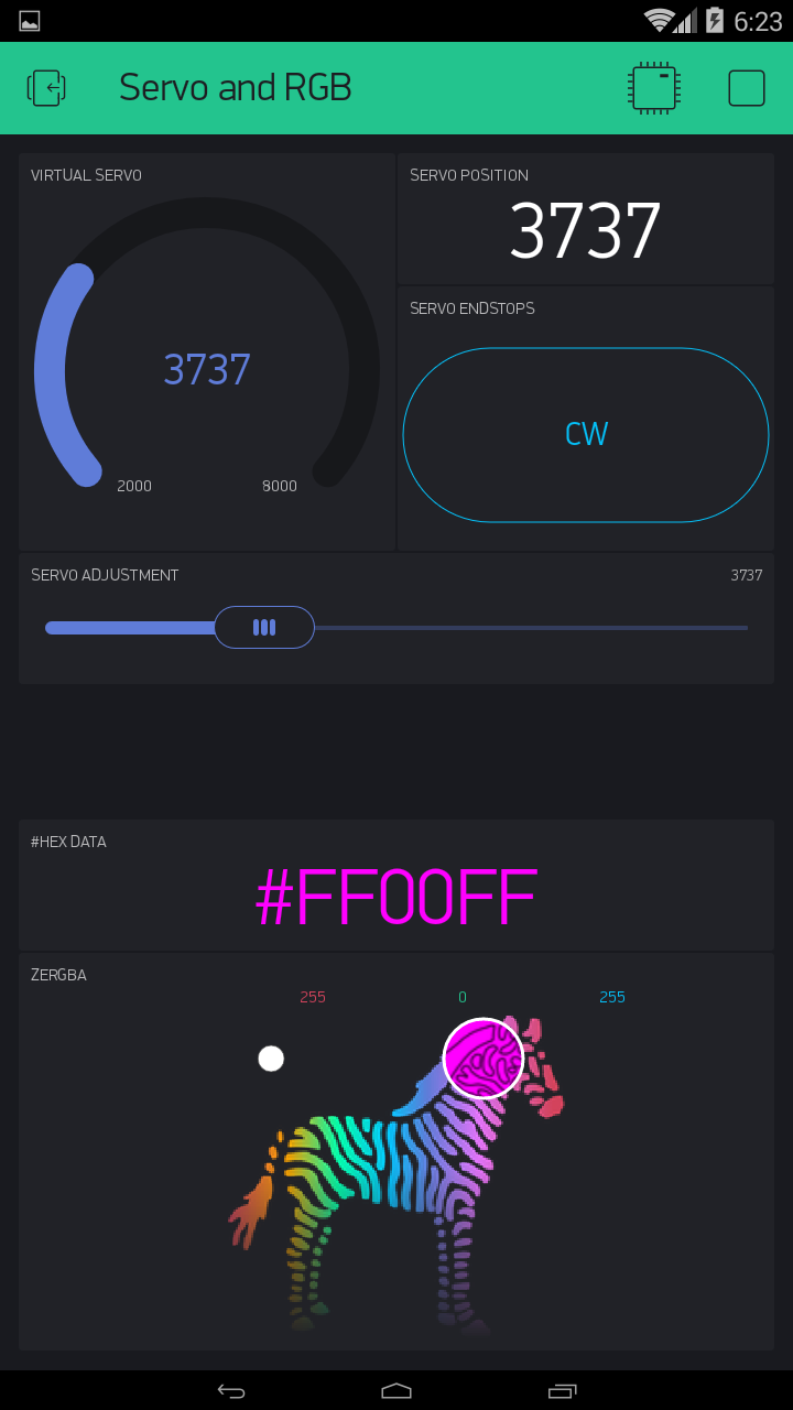
image

//#define BLYNK_PRINT Serial // This prints to Serial Monitor

#include <WiFi.h>
#include <WiFiClient.h>
#include <BlynkSimpleEsp32.h>

#include <ESPmDNS.h>  // For OTA - ESP32
#include <WiFiUdp.h>  // For OTA
#include <ArduinoOTA.h>  // For OTA

#include "esp32-hal-ledc.h" // For Servo & RGB PWM control

char auth[] = "xxxxxxxxxx";
char ssid[] = "xxxxxxxxxx";
char pass[] = "xxxxxxxxxx";
//char server[] = "xxx.xxx.xxx.xxx";  // IP for your Local Server
char server[] = "blynk-cloud.com";  // URL for Blynk Cloud Server
int port = 8080;

int rrr, ggg, bbb;  // Set RED BLUE GREEN channe
int ServoPos;


void setup() {
  //Serial.begin(115200);  // BLYNK_PRINT data

  //===== Servo pin setup for ESP32 =====
  ledcSetup(1, 50, 16); // For Servo - channel 1, 50 Hz, 16-bit width
  ledcAttachPin(2, 1);   // For Servo - GPIO 2 assigned to channel 1

  //===== RGB LED pin setup for ESP32 =====
  ledcSetup(2, 5000, 8); // For RGB-Red - channel 2, 5000 Hz, 8-bit width
  ledcAttachPin(25, 2);   // For RGB-Red - GPIO 25 assigned to channel 2

  ledcSetup(3, 5000, 8); // For RGB-Green - channel 3, 5000 Hz, 8-bit width
  ledcAttachPin(27, 3);   // For RGB-Green - GPIO 27 assigned to channel 3

  ledcSetup(4, 5000, 8); // For RGB-Blue - channel 4, 5000 Hz, 8-bit width
  ledcAttachPin(26, 4);   // For RGB-Blue - GPIO 26 assigned to channel 4


  WiFi.begin(ssid, pass);
  Blynk.config(auth, server, port);
  Blynk.connect();

  ArduinoOTA.setHostname("ESP32 Servo RGB");  // For OTA - Use your own device identifying name
  ArduinoOTA.begin();  // For OTA
}


//===== Servo Control Widgets =====
BLYNK_WRITE(V1) {  // Slider for selective servo positioning
  ServoPos = param.asInt();  // Get position data
  ledcWrite(1, ServoPos);  // Move servo to position
  Blynk.virtualWrite(V0, ServoPos);  // Display servo position
  Blynk.virtualWrite(V5, ServoPos);  // Show servo position
}  // END Blynk Function


BLYNK_WRITE(V2) {  // Button for servo endstop positioning
  ServoPos = param.asInt();  // Get position data (pre set in MIN/MAX settings
  ledcWrite(1, ServoPos);  // Move servo to position
  Blynk.virtualWrite(V0, ServoPos);  // Display servo position
  Blynk.virtualWrite(V5, ServoPos);  // Show servo position
  Blynk.virtualWrite(V1, ServoPos);  // Sync slider position
}  // END Blynk Function


//===== zeRGBa Widget =====
BLYNK_WRITE(V4) { // START Blynk Function
  rrr = param[0].asInt(); // get a RED channel value
  ggg = param[1].asInt(); // get a GREEN channel value
  bbb = param[2].asInt(); // get a BLUE channel value
  RGBprocess(); // Run Arduino funtion
}  // END Blynk Function


//===== Physical RGB LED Control and HEX conversion =====
void RGBprocess() {  // START Arduino funtion

  // For Common Anode+ RGB LED
  ledcWrite(2, 256 - rrr); // Write to RED RGB pin
  ledcWrite(3, 256 - ggg); // Write to GREEN RGB pin
  ledcWrite(4, 256 - bbb); // Write to BLUE RGB pin

  // For Common Cathode- RGB LED
  //  ledcWrite(2, rrr); // Write to RED RGB pin
  //  ledcWrite(3, ggg); // Write to GREEN RGB pin
  //  ledcWrite(4, bbb); // Write to BLUE RGB pin

  // zeRGBa pin to #HEX conversion
  String strRED = String(rrr, HEX);  // Convert RED DEC to HEX
  if (rrr < 16) {
    strRED = String("0" + strRED);  // Buffer with 0 if required
  }  // END if
  String strGRN = String(ggg, HEX);  // Convert GREEN DEC to HEX
  if (ggg < 16)  {
    strGRN = String("0" + strGRN);  // Buffer with 0 if required
  }  // END if
  String strBLU = String(bbb, HEX);  // Convert BLUE DEC to HEX
  if (bbb < 16)  {
    strBLU = String("0" + strBLU);  // Buffer with 0 if required
  }  // END if
  String HEXstring = String("#" + strRED + strGRN + strBLU);  // Combine HEX fragments
  HEXstring.toUpperCase();  // Change HEX value to all upper case for ease of visuals.
  Blynk.setProperty(V3, "color", HEXstring);  // Change background colour of HEX Data Label
  Blynk.virtualWrite(V3, HEXstring);  // Display HEX data
}  // END Arduino Function


void loop() {
  Blynk.run();
  ArduinoOTA.handle();  // For OTA
}
6 Likes

#15 - Dual Blynk sliders for High Range High Precision values

And for all those precision slider fanatics who want their cake and eat it too (PS the cake is a lie :wink: )…

I introduce the solution for High Range AND High Precision using only sliders (no ugly step widgets for analog purists :stuck_out_tongue: ) Good luck trying to do both with a single slider.

int FullRange;
float Precision;

BLYNK_WRITE(V0) {  // Higher Range slider 0 to 255
  Blynk.virtualWrite(V1, 0);  // Zero out Precision slider
  FullRange = param.asInt();
  Blynk.virtualWrite(V2, FullRange);  // Display widget
}

BLYNK_WRITE(V1) {  // High Precision slider -0.99 to 0.99
  Precision = param.asFloat();
  Blynk.virtualWrite(V2, FullRange + Precision);  // Display widget
}

image

image

image

image

10 Likes

#16 - Ultrasonic Distance Sensor with Servo

This little project used the HC-SR04 Ultrasonic sensor… but instead of boring old distance numbers, it will also position a servo within a range of selected distances.

This sketch demonstrates a timer that can be enabled and disabled, so as not to be running something like the Ultrasonic sensor if other critical timing functions need to run.

And also demonstrates enabling and disabling the servo, so that there is no jitter or fluttering when it is not supposed to be moving, as can sometimes be caused by other timer routines.

Sensor and Servo need 5v, so best to draw from a separate 5v PSU than the Wemos’s 5v pin… particularly for the servo.

Wire the sensor and servo pins as shown in the sketch.

int trigPin = 12;  // D5 on Wemos D1 Mini
int echoPin = 13;  // D6 on Wemos D1 Mini
int servoPin = 4;  // D2 on Wemos D1 Mini

As a precaution, I wired a 1K resistor in series between the ECHO pin of the sensor and Pin 13 (D7) of the Wemos… this drops the current potential down, so that the 5v signal will not hurt the Wemos.

//#define BLYNK_PRINT Serial
#include <ESP8266WiFi.h>
#include <BlynkSimpleEsp8266.h>

#include <ESP8266mDNS.h>  // For OTA
#include <WiFiUdp.h>  // For OTA
#include <ArduinoOTA.h>  // For OTA

#include <Servo.h>

char auth[] = "xxxxxxxxxx";  // Local Server
char ssid[] = "xxxxxxxxxx";
char pass[] = "xxxxxxxxxx";
//char server[] = "xxx.xxx.xxx.xxx";  // IP for your Local Server
char server[] = "blynk-cloud.com";
int port = 8080;

int trigPin = 12;  // D5 on Wemos D1 Mini
int echoPin = 13;  // D6 on Wemos D1 Mini
int servoPin = 4;  // D2 on Wemos D1 Mini

int PingTimer; // TimerID
int SrvoPos;  // Servo position
long duration, distance;  // For Ping sensor 

BlynkTimer timer;
Servo myservo;


void setup() {
  //Serial.begin(115200);
  pinMode(trigPin, OUTPUT);
  pinMode(echoPin, INPUT);
  pinMode(servoPin, OUTPUT);

  WiFi.begin(ssid, pass);
  Blynk.config(auth, server, port);
  Blynk.connect();

  // ===== Timer Setup =====
  PingTimer = timer.setInterval(250L, PingSensor);  // Ping distance routine - Button Controlled
  timer.disable(PingTimer);  // Disable timer until needed

  ArduinoOTA.setHostname("Wemos D1 Mini");  // For OTA - Use your own device identifying name
  ArduinoOTA.begin();  // For OTA
}


BLYNK_CONNECTED() {
    Blynk.syncVirtual(V2)
}


void loop() {
  Blynk.run();
  timer.run(); // Initiates BlynkTimer
  ArduinoOTA.handle();  // For OTA
}


BLYNK_WRITE(V2) { // Button to Enable/Disable Ultrasonic Sensor Routine
  if (param.asInt() == 1) {  // If button state is 1 (HIGH) then...
    timer.enable(PingTimer);  // Enable timer
    myservo.attach(servoPin);  // Connect survo
  } else {  // If button state is 0 (LOW) then...
    timer.disable(PingTimer);  // Disable timer
    myservo.write(5);  // Set servo at 0 position
    Blynk.virtualWrite(V1, 0);  // Reset Gauge for servo position
    Blynk.virtualWrite(V0, "N/A");  // Reset Display for Ultrasonic Sensor status
    delay(500);  // Small delay to allow servo reposition before disabling it.
    myservo.detach();  // Disconnect survo
  }
}


void PingSensor() {  // Ultrasonic (Ping) Distance Sensor
    // Pulse
    digitalWrite(trigPin, LOW);
    delayMicroseconds(2);
    digitalWrite(trigPin, HIGH);
    delayMicroseconds(10);
    digitalWrite(trigPin, LOW);

    // End Pulse & Calculate didtance
    duration = pulseIn(echoPin, HIGH);
    distance = (duration / 2) / 29.1;

    // Map and constrain the Ultrasonic range 1-50cm to the servo position of 10-160
    SrvoPos = constrain(map(distance, 1, 50, 10, 160), 10, 160);  

    // Show results
    myservo.write(SrvoPos);  // Position servo
    Blynk.virtualWrite(V0, distance);  // To Display Widget
    Blynk.virtualWrite(V1, SrvoPos);  // To Gauge Widget
}
5 Likes

#17 - Dual Temperature Sensors running on ESP-01

This is a simple example of running both a DHTxx (in this case DHT11) and DS18B20 1-wire sensors on the lowly ESP-01

#include <ESP8266WiFi.h>
#include <BlynkSimpleEsp8266.h>

#include <ESP8266mDNS.h>  // For OTA
#include <WiFiUdp.h>  // For OTA
#include <ArduinoOTA.h>  // For OTA

char auth[] = "xxxxxxxxxx";  // Local Server
char ssid[] = "xxxxxxxxxx";
char pass[] = "xxxxxxxxxx";
//char server[] = "xxx.xxx.xxx.xxx";  // IP for your Local Server
char server[] = "blynk-cloud.com";
int port = 8080;

BlynkTimer timer;

// DHT22 Sensor setup
#include <DHT.h>
#define DHTPIN 0  // GPIO0 - pin5 on ESP-01
#define DHTTYPE DHT11
DHT dht(DHTPIN, DHTTYPE);
float h;
float t;

// DS18B20 Sensor setup
#include <OneWire.h>
#include<DallasTemperature.h>
#define ONE_WIRE_BUS 2  // GPIO2 - pin3 on ESP-01
OneWire oneWire(ONE_WIRE_BUS);
DallasTemperature DS18B20(&oneWire);
float DS18B20Temp;


void setup()
{
  DS18B20.begin();

  Blynk.connectWiFi(ssid, pass);
  Blynk.config(auth, server, 8080);
  Blynk.connect();

  timer.setInterval(1000L, UpTime);
  timer.setInterval(60000L, DS18B20TempSensor);
  timer.setInterval(10050L, DHTTempHumSensor);

  Blynk.virtualWrite(2, BLYNK_VERSION);
  Blynk.virtualWrite(6, ESP.getCoreVersion());

  ArduinoOTA.setHostname("ESP-01 Multi-temp");  // For OTA
  ArduinoOTA.begin();  // For OTA
}


void DS18B20TempSensor()  // DS18B20 sensor reading
{
  DS18B20.requestTemperatures();
  delay(500);  // Yes, the evil delay... but only for a really short time every 10s .  Alternative options are avail with timers.
  Blynk.virtualWrite(V3, DS18B20.getTempCByIndex(0));
}


void DHTTempHumSensor()  // DHT sensor reading
{
  h = dht.readHumidity();
  t = dht.readTemperature(); // or dht.readTemperature(true) for Fahrenheit
  Blynk.virtualWrite(V4, h);
  Blynk.virtualWrite(V5, t);
}


BLYNK_WRITE(V1) {  // Quick test read.  Clears all values and reloads
  if (param.asInt()) {
    Blynk.virtualWrite(V0, 0);
    Blynk.virtualWrite(V3, 0);
    Blynk.virtualWrite(V4, 0);
    Blynk.virtualWrite(V5, 0);
    DS18B20TempSensor();
    DHTTempHumSensor();
  }
}


void UpTime()
{
  Blynk.virtualWrite(V0, millis() / 1000);
  Blynk.virtualWrite(V7, WiFi.RSSI());
}


void loop()
{
  Blynk.run();
  timer.run();
  ArduinoOTA.handle();  // For OTA
}
8 Likes

#18 - Multi Colour Button, one color for ON one for OFF

NOTE - This has been rendered obsolete with the new Styled Button :+1:


The button (in switch mode) is essentially ON all the time, but pressing it toggles a variable (buttonState) between 0 & 1 so you can still control things outside the Blynk Function if you want.

You can also change the small labeling… However, there is no current way, that I am aware of, to change the buttons center text from within code.

You can make both ON and OFF colours whatever you want… just use my zeRGBa examples above to get the #HEX code you need for the colour you want.

In pre-setup…

int buttonToggle = 1;  // Set buttonToggle to 1 to start buttonState in OFF mode
int buttonState = 0;  // Set buttonState variable OFF

In setup after connection…

Blynk.virtualWrite(V0, 1); // set coloured button to default ON state
BLYNK_WRITE(V0) {
  if (param.asInt() == 0 && buttonToggle == 1) {
    buttonToggle = 0;
    buttonState = 1;
    Blynk.setProperty(V0, "color", "#23C48E"); // GREEN
    Blynk.setProperty(V0, "label", "ON"); // ON
  } else if (param.asInt() == 0 && buttonToggle == 0) {
    buttonToggle = 1;
    buttonState = 0;
    Blynk.setProperty(V0, "color", "#D3435C"); // RED
    Blynk.setProperty(V0, "label", "OFF"); // OFF
  }
  Blynk.virtualWrite(V1, buttonState);  // Display buttons usable state
  Blynk.virtualWrite(V0, 1);  // reset button widget to ON
}

5 Likes

A post was merged into an existing topic: Blynk.setProperty() command not changing button color

A post was split to a new topic: How to repeat the same activity or stop the activity form a function that is called by a BLYNK_WRITE(V?) function

#19 - Modified Text Input Widget performance - Now with 100% more line feed :stuck_out_tongue:

Well, here is another modification to make a widget work how I at least think it could (and possibly temporary… see my supplanted multi-coloured button above :wink: )

NOTE: This is NOT intended to undermine what Blynk has made… just add in my own personal preferences to somthing I wish to use in a particular way.

The text Input widget is great… easy to use and compact, compared to the Terminal input option. Only one thing… It doesn’t act like a ‘true’ (IMHO) text input. No EOL, ‘carriage return’ or clearing upon hitting return. All by design? Perhaps :smiley:

Well, here is my simple code mod to supply all those “missing” features :sunglasses:

You can still use the Widget as intended, or with the addition of a space and two periods (customisable) followed by the return key. you can get a cleared widget and a new line in the resulting string.

Due to the need for a SPACE to “clear” the widget… some post processing is used to remove a single leading SPACE from your string, if present.

String textIn; // declare global variable

//===== Modified Text Input Widget - BLYNK Function =====
BLYNK_WRITE(V0) {
  String textIn = param.asStr(); // Get string from Text Input Widget
  if (textIn.startsWith(" ")) {  // If it has a leading SPACE...
    textIn.remove(0, 1);  // ...remove it.
  }
  if (textIn.endsWith(" ..")) {  // If it has customisable EOL indicator, In my case SPACE and 2 PERIODS...
    textIn.replace(" ..", "\n"); // ...replace with newline command
    Blynk.virtualWrite(V0, " ");  // "clear" the Text Input field.  A null "" will not work, so needs a space
  }
  Serial.print(textIn);  // Show string output as intended, or do whatever you want with the string.
  Blynk.virtualWrite(vPin, textIn);  // Like send it to a terminal Widget
}

So if you want or need a truer text entry feeling, with carriage return effects… this…

image

…can become this, just by ending with a SPACE and 2 PERIODS (customisable)

image

image

image

To give this output…

image


And for the fun of it, here is some code to add a Clear Terminal button.

//===== Clear Terminal Widget =====
BLYNK_WRITE(vPin) {  // Button Widget
  if (param.asInt()) {
    Blynk.virtualWrite(vPin, "clr");  // Clears terminal if button state is 1
  }
}

image

3 Likes

5 posts were merged into an existing topic: Server connection dropouts

#20 - Variable timer

There has been a few discussions about how to vary the interval time of a timer… I have even used one way in an earlier post above with the adjustable servo sweep.

But here is an easier way… use a one-shot Timeout Timer instead…

Create your function that you want to run on a variable interval, but don’t call that function with an outside timer, just call it the first time (if you want) in your setup or upon Blynk connect, or even wait until you chose a time, etc.

Then, using a global variable acquired from some other source (Slider, Step Control, Numeric input, etc.) end your custom timed function with a timeout timer, set to the required variable, that calls the same function it is already in.

If you really want to get fancy, you can setup Timer IDs and run a delete timer at the beginning of the function, thus allowing you to interrupt and cancel whatever previous setting… preventing duplicate function runs from leftover timeout timers.

long variableTime = 1000; // default interval time of 1 second
int varTimer;  // Setup Timeout Timer ID 
BLYNK_WRITE(V0) { // Widget for interval timing
  variableTime = param.asInt();
  if (variableTime <= 0) { // prevents a timer from becoming 0 or less
    variableTime = 1;
  }
  timerLoop();  // Call your timed loop
}


void timerLoop() {
  timer.deleteTimer(varTimer);  // Cancel previous Timeout Timer
  //  
  //  Do your stuff here every (variableTime) seconds
  //
  varTimer = timer.setTimeout(variableTime, timerLoop);  // Set new Timeout timer
}
9 Likes

#21 - Sonoff Basic - Blynk and physical button control - with LED (showing ON status), OTA and displaying device specifics.

This is just a simple sketch for a Blynkified Sonoff Basic. Use either App or physical button to toggle the Sonoff. Physical button works even if no Server connected.

/*
   Sonoff Basic
   1MB (No SPIFS) flash size
   115200 BAUD
   MUST USE DOUT for Flash Mode!!

   sonoff header
   1 - vcc 3v3
   2 - rx
   3 - tx
   4 - gnd
   5 - gpio 14

   esp8266 connections
   gpio  0 - button
   gpio 12 - relay
   gpio 13 - green led - active low
   gpio 14 - pin 5 on header
*/

#include <ESP8266WiFi.h>  // for ESP8266
#include <BlynkSimpleEsp8266.h>  // for ESP8266
#include <ESP8266mDNS.h>  // For OTA w/ ESP8266
#include <WiFiUdp.h>  // For OTA
#include <ArduinoOTA.h>  // For OTA

char auth[] = "xxxxxxxxxx";  // Sonoff
char ssid[] = "xxxxx";
char pass[] = "xxxxx";
char server[] = "xxx.xxx.xxx.xxx";  // IP for your Local Server
int port = 8080;

int pinState = LOW;
int btnState = HIGH;

BlynkTimer timer;
void PhysButton();

void setup() {
  pinMode(0, INPUT);
  pinMode(12, OUTPUT);
  pinMode(13, OUTPUT);
  digitalWrite(13, HIGH);  // Turn OFF LED

  timer.setInterval(250L, PhysButton);  // scan for physical button press

  WiFi.begin(ssid, pass);
  Blynk.config(auth, server, port);
  Blynk.connect();

  ArduinoOTA.setHostname("Sonoff");  // For OTA - Use your own device identifying name
  ArduinoOTA.begin();  // For OTA
}


void loop() {
  Blynk.run();
  timer.run();
  ArduinoOTA.handle();  // For OTA
}


BLYNK_CONNECTED() {
  Blynk.syncVirtual(V0);
  Blynk.virtualWrite(V1, BLYNK_VERSION);
  Blynk.virtualWrite(V2, ESP.getCoreVersion());
  Blynk.virtualWrite(V3, WiFi.macAddress());
  Blynk.virtualWrite(V4, WiFi.localIP().toString());
}


BLYNK_WRITE(V0) { // Button Widget in switch mode
  digitalWrite(12, param.asInt());  // Toggle relay
  digitalWrite(13, !param.asInt());  // Toggle LED
}

void PhysButton() {
  if (digitalRead(0) == LOW) {
    // btnState is used to avoid sequential toggles
    if (btnState != LOW) {

      // Toggle LED state
      pinState = !pinState;
      digitalWrite(12, pinState);
      digitalWrite(13, !pinState);  // Toggle LED

      // Update Button Widget
      Blynk.virtualWrite(V0, pinState);
    }
    btnState = LOW;
  } else {
    btnState = HIGH;
  }
}

My simple display used to fit everything the way I wanted (centered columns under the buttons)… but now it looks lopsided with extended displays, that still crop on some devices… Boo!! Hiss!!

The sketch fits on the Sonoff, with a bit of room for more code :smiley:

9 Likes