I thought I’d write a guide about how to use virtual pins with app widgets such as buttons, to control physical devices such as relays, LEDs etc…
Why use virtual pins anyway?
I’d always recommend using virtual pins over physical pins when developing your code. There are a number of reasons, but here are what I consider to be the main ones:
- Virtual pins are hardware independent. This means that it’s far easier to port your code from one hardware platform to another in future (when you realise that the NodeMCU is far better than the Arduino Uno + ESP-01 that you started with, for example).
- You have far more control over what your widget does when using using virtual pins. For example, if you want a single app button to switch multiple relays on or off at the same time then that’s simple with virtual pins, but almost impossible using digital pins.
- In my experience, virtual pins are more predictable (stable if you like) than manipulating digital pins via the app.
So what are virtual pins - how do they relate to the pins on my board?
Virtual pins are really just a way of sending a message from the app to the code that’s running on your board (via the Blynk server).
There is absolutely no correlation between virtual pins and any of the physical pins on your board. If you want a virtual pin to change the state of one of your physical pins then you have to write the code to make this happen. But don’t panic, it’s not difficult that difficult! - just keep reading…
Basic principals of using virtual pins
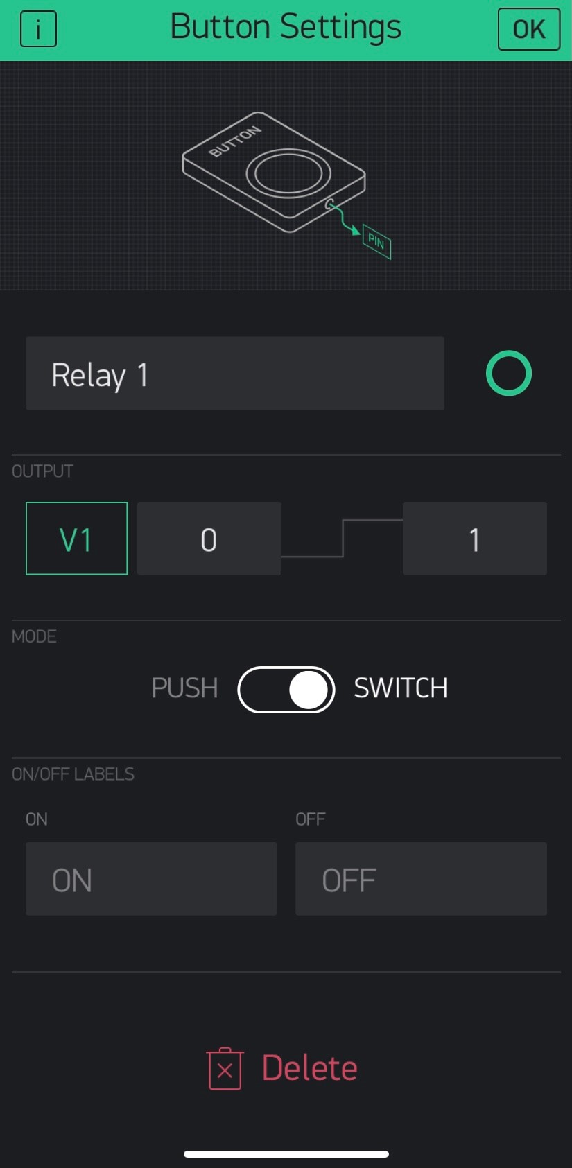
We’ll use an example of a button widget, set to Switch mode, connected to Virtual Pin 1 (V1). In the app we’ll leave the Output values set to the default of 0 and 1, so the widget sends a 0 when it’s turned off, and a 1 when it’s turned on - like this…
The BLYNK_WRITE(vPin) function
In your C++ sketch you can add a special function that is triggered automatically whenever the server tells your device that the value of your virtual pin has changed. This change would normally happen when the widget button in the app is pressed.
This special function is called BLYNK_WRITE, but it’s name is is a little confusing. Think of it as meaning that the server is telling your hardware “someone has written a new value to your virtual pin”.
So, for virtual pin 1, our sketch would need this bit of code adding…
BLYNK_WRITE(V1)
{
  // any code you place here will execute when the virtual pin value changes
}
That’s okay if you want the same code to execute regardless of whether the button widget was turned on or off, but that’s not much use in real life, so we need to find out what the new value of the virtual pin is. Don’t forget, this will be a 0 if the button widget is off, and a 1 of it’s on.
Obtaining values from the virtual pin
The server sends the current virtual pin value to the hardware as a parameter, and this can be obtained from within the BLYNK_WRITE(vPin) function with a piece of code like this…
int virtual_pin_value = param.asInt();
This tells the code to get the value parameter from the virtual pin and store it in the local integer variable called virtual_pin_value.
We can then use this value to do different actions if the button widget is now on, compared to if it is now off.
Some widgets send their values at text, or floating point numbers (Integers are whole numbers, floating point variables are ones with numbers to the right of the decimal point).
To allow you to use these values the Blynk library also allows the following:
param.asStrng()
param.asFloat()
but, as we are dealing with just zeros and ones, which are integers, we’ll use the param.asInt method.
But how do we control the physical hardware pins on my board?
If you’re familiar with C++/Arduino programming you’ll probably know about pinMode and digitalWrite commands already. These are what we use to control the physical pins of your device from within the BLYNK_WRITE(vPin) function.
For those people who aren’t familiar with these commands I’ll give a brief summary here - but feel free to learn more by searching the internet.
The pinMode command tells your board how a particular pin is going to be used. The three most common commands are:
pinMode(pin, OUTPUT);
pinMode(pin, INPUT);
pinMode(pin, INPUT_PULLUP);
As we will be controlling something like a relay or an LED in this example, we want our pins to be OUTPUTs - we’ll be outputting a HIGH or LOW signal to the relay/LED.
You only need to issue a pinMode command once, when your device boots up, so this command goes in your void setup()
The digitalWrite(pin,value) command sets the specified pins LOW (zero volts) or HIGH (3.3v or 5v, depending on your type of board). This is how you energise your relay, LED etc.
Bringing it all together…
This example code assumes that we want to control digital pin 2 on your board…
void setup()
{
  pinMode(2, OUTPUT); // Initialise digital pin 2 as an output pin
}

BLYNK_WRITE(V1) // Executes when the value of virtual pin 1 changes
{
  if(param.asInt() == 1)
  {
    // execute this code if the switch widget is now ON
    digitalWrite(2,HIGH);  // Set digital pin 2 HIGH
  {
  else
  {
    // execute this code if the switch widget is now OFF
    digitalWrite(2,LOW);  // Set digital pin 2 LOW
  }
}
Note that you can only have one void setup() in your sketch, so the pinMode statement needs to be copied into your existing void setup()
That’s it really, you now have the same functionality from your virtual pin as you would have had if you’d used a digital pin.
I’m now going to cover some extra stuff - some of which is specific to working with virtual pins, but some also applies if you use digital pins instead…
Extra stuff to look out for…
Dealing with Active LOW devices - Many devices, such as the onboard LED attached to GPIO2 of the NodeMCU and many relay boards, are energised by a LOW signal rather than a HIGH signal. This means that, if you use the code example above, the LED/Relay will be off when the switch widget shows On, and vice-versa.
There are several ways around this issue. You could change your switch widget output settings to be 1/0 rather than 0/1 - so that an On state send a “0” value to the app like this…
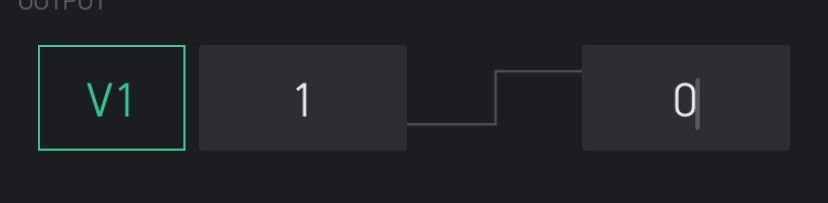
Personally, I don’t like this approach and would prefer to modify the code by swapping all the digitalWrite LOW commands with HIGH and vice-versa.
Synchronising the output state with the app at startup - When the device starts-up (reboots) it won’t be aware of the state of the button widget in the app, so may be in a different state to what the button widget shows in the app. This will be rectified when you toggle the button widget in the app, but that’s not a very satisfactory solution.
We can force the Blynk server to send the latest value for the virtual pin, by using the Blynk.syncVirtual(vPin) command. This causes the corresponding BLYNK_WRITE(vPin) command to execute.
To automatically run the BlynkSyncVirtual(vPin) command when the device connects to the Blynk server (which will normally be after a reboot, but could also be following a disconnection) we can use another special function called BLYNK_CONNECTED, like this…
BLYNK_CONNECTED()
{
  Blynk.syncVirtual(V1);  // will cause BLYNK_WRITE(V1) to be executed
}
There is also a function called Blynk.syncALL() which will cause the server to send the value of all virtual and digital pins to the hardware. However, this function can take a while to execute, and should be avoided whenever possible. It’s only really necessary if digital pins need to be synchronised, and hopefully you’re moving towards using virtual pins in the app rather than digital pins.
Pin numbering - If you’re working with an Arduino then it’s all quite simple. General Purpose Input/Output (GPIO) pin 2 is labelled “2” or “D2”.
However, if you’re using a NodeMCU type of device then the manufacturers decided to make things a little more complicated. The numbers screen printed onto the board are not the GPIO numbers. You have to translate these NodeMCU “D” numbers onto actual GPIO’s as follows…
Lablel GPIO
D1 5
D2 4
D3 0
D4 2
D5 14
D6 12
D7 13
D8 15
So, in the example above where we controlled GPIO2 with the command digitalWrite(2,HIGH) it’s actually the pin labelled “D4” on the NodeMCU that we’re turning on and off.
The Arduino IDE does allow you to use the NodeMCU’s “D” pin numbers directly rather than GPIOs, like this:
digitalWrite(D4,HIGH);
but personally I don’t like this approach as it makes it much more difficult to use your code on different types of devices if you ever need to.
Some NodeMCU physical pins need to be a avoided - Some of the pins on the NodeMCU aren’t really suitable for connecting some types of devices to. In particular, if GPIO0 (the pin labelled D3) is pulled LOW at startup then the device won’t execute the sketch and instead it will enter programming mode, waiting for a new sketch to be uploaded. There’s more info in this topic:
You said “if you want a single app button to switch multiple relays on or off at the same time then that’s simple with virtual pins” but how do we do that? - It really is very simple. Lets say that you have four relays that are all controlled by four different button widgets attached to virtual pins (V1 to V4). These allow independent control of each of the relays, but you then want another button widget, which we’ll attach to virtual pin 5, that can turn all of the relays on or off with just one click.
When this button turns on/off all of the relays it also needs to update the 4 button widgets (attached to V1 to V4), so that they are also all on or off.
Here’s what the BLYNK_WRITE(V5) function would look like to do this…
BLYNK_WRITE(V5) // Executes when the value of virtual pin 5 changes
{
  if(param.asInt() == 1)
  {
    // execute this code if the switch widget is now ON
    digitalWrite(2,HIGH);  // Set digital pin 2 HIGH
    digitalWrite(4,HIGH);  // Set digital pin 4 HIGH
    digitalWrite(5,HIGH);  // Set digital pin 5 HIGH
    digitalWrite(12,HIGH);  // Set digital pin 12 HIGH

    Blynk.virtualWrite(V1,1);  // Turn the widget attached to V1 On
    Blynk.virtualWrite(V2,1);  // Turn the widget attached to V2 On
    Blynk.virtualWrite(V3,1);  // Turn the widget attached to V3 On
    Blynk.virtualWrite(V4,1);  // Turn the widget attached to V4 On
  {
  else
  {
    // execute this code if the switch widget is now OFF
    digitalWrite(2,LOW);  // Set digital pin 2 LOW
    digitalWrite(4,LOW);  // Set digital pin 4 LOW
    digitalWrite(5,LOW);  // Set digital pin 5 LOW
    digitalWrite(12,LOW);  // Set digital pin 12 LOW

    Blynk.virtualWrite(V1,0);  // Turn the widget attached to V1 Off
    Blynk.virtualWrite(V2,0);  // Turn the widget attached to V2 Off
    Blynk.virtualWrite(V3,0);  // Turn the widget attached to V3 Off
    Blynk.virtualWrite(V4,0);  // Turn the widget attached to V4 Off
  }
}
As you can see, instead of just doing a digitalWrite to one GPIO pin, we’re doing 4 digitalWrites one after another. The Blynk.virtualWtite commands are then issued, which will update the button widgets to match the digital pins (so that the button widgets attached to virtual pins V1 to V4 show the same status as our ‘master’ button widget attached to virtual pin V5).
And that’s your crash course in using virtual pins to control physical devices ![]()
I’ll leave this topic open for comments, as I’d like to know if there are any mistakes, ambiguities or important areas that I’ve forgotten to cover.
However, I’d like the topic to be a simple reference for others to follow, so don’t want it to be cluttered-up with “this is my sketch, but it’s not working, please fix it for me” type of comments. If you post these types of comments then they will either be split-off into new topics, or simply deleted.
Thanks for reading, and have fun in your new virtual world!
Update for Blynk 2.0…
This topic was originally written before Blynk 2.0 (Blynk IoT) was launched, and although the basic principals are the same, there are several changes that users should be aware of…
Only Virtual pins are supported in Blynk 2.0 at the moment
At the time of this update (July '21) Blynk 2.0 only supports virtual pins.
Defining Datastreams
Datastreams need to be defined in the web dashboard, before they can be used with devices in either the app, the web dashboard, or in your sketch.
When you create a datastream in the web dashboard you link it to a virtual pin and give it a name. Fort example, you might create a datastream called “Temperature” linked to pin V1
This name “Temperature” is what you see in the app and web dashboard when you’re selecting the datastream to use, but you still refer to it as V1 in your sketch.
Datastream min/max values
By default, integer and float datastream types default to having a minimum value of 0, and a maximum value of 1.
Any values outside of these min/max thresholds will be ignored, so bear this in mind when defining your datastreams.
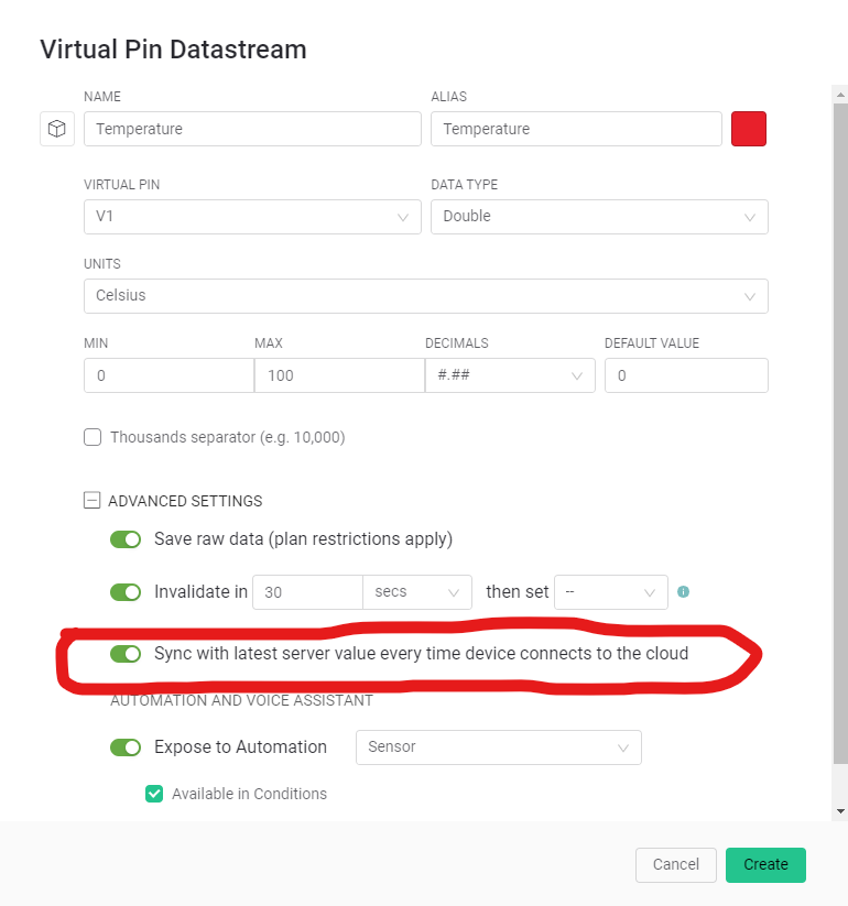
Blynk.syncAll no longer synchronises everything!
As I said earlier, Blynk 2.0 only supports virtual pins at the moment, but using Blynk.syncAll() will not cause all virtual pins to be synchronised.
Only pins that have a tick in this checkbox will be included in the Blynk.syncAll() command:
Documentation for Virtual Pins in Blynk 2.0 is here:
https://docs.blynk.io/en/blynk.edgent/mainoperations/virtual-pins
Pete.