Node-RED is a great solution, tasker is also a very good solution as well, I tried both of them and both worked flawlessly.
1 Like
Yes I’m sure, but I am software engineer so I prefer hard-coding 
1 Like
Node-Red gives a hard-coded solution.
Pete.
2 Likes
Thanks all, i’ll check the solutions you’ve suggested. Getting data from all devices to a single controller will definitely improve my project. I’ll also consider using the legacy version since the bridge widget gives another solution.
Thanks for the help
1 Like
I don’t recommend this move, blynk legacy will be retired soon.
Thanks, i’ll drop this option ![]()
I’ll use this post for further question about automation. I cant seem to understand how should I update a device when action occurs.
For example, I have a humidity device with a relay and ESP8266 that I want to turn on when another device send low humidity %.
So I understand how to set up the data streams on both device and set up an action, I don’t understand how this action will change the state of the relay.
Should I read the virtual pin connected to the data stream?
Thanks again.
I have, and I am setting everything as described, just the part where I want to change the relay state, this I don’t understand how it is done.
Where is the connection between the data stream that is defined to change switch when action occurs to the relay.
Hope i’m clear… thanks for the help.
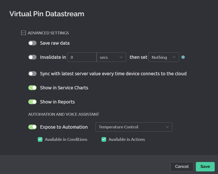
If you cant choose the device/datastream that you want to control with the automation then you probably haven’t configured that target datastream correctly in the Advanced settings
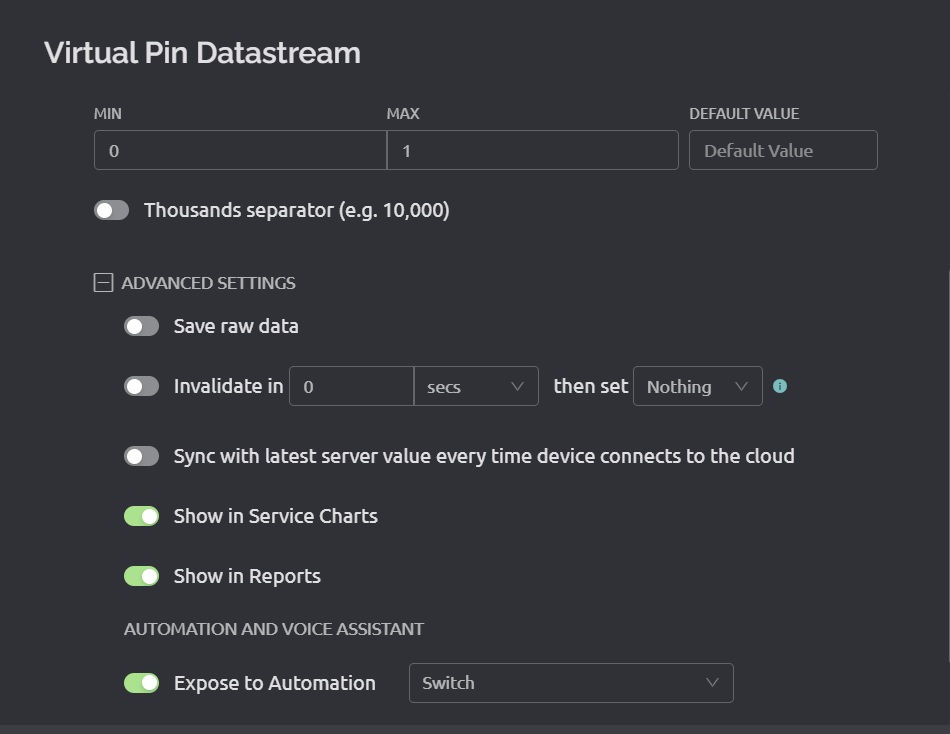
In the Expose to Automations part, you’ll need the target device configured as a Switch, and Available in Actions checked.
Pete.
@PeteKnight I can see the device and data stream and configured it as you suggested.
@John93 Yes, I’m configuring something like this, just not sure how exactly the data is updated in the sending and receiving side. I’m missing something…
You need to describe in detail what your setup is, what datasteams you’ve defined, and what you’ve done so fat with the automations.
Without this information we’re just guessing.
Pete.
I have two templates, A and B.
Template A has data stream on V1 defined as integer and enabled as Expose to Automation - Temperature control.
Template B has data stream V2, integer, defined also enabled and configured as switch.
Device “Send” is connected to template A and receives data from a sensor. The data should be transmitted as Blynk.virtualWrite(V1, humidity); (?)
Device “Receive” is connected to template B and needs to operate a relay that is connected to it.
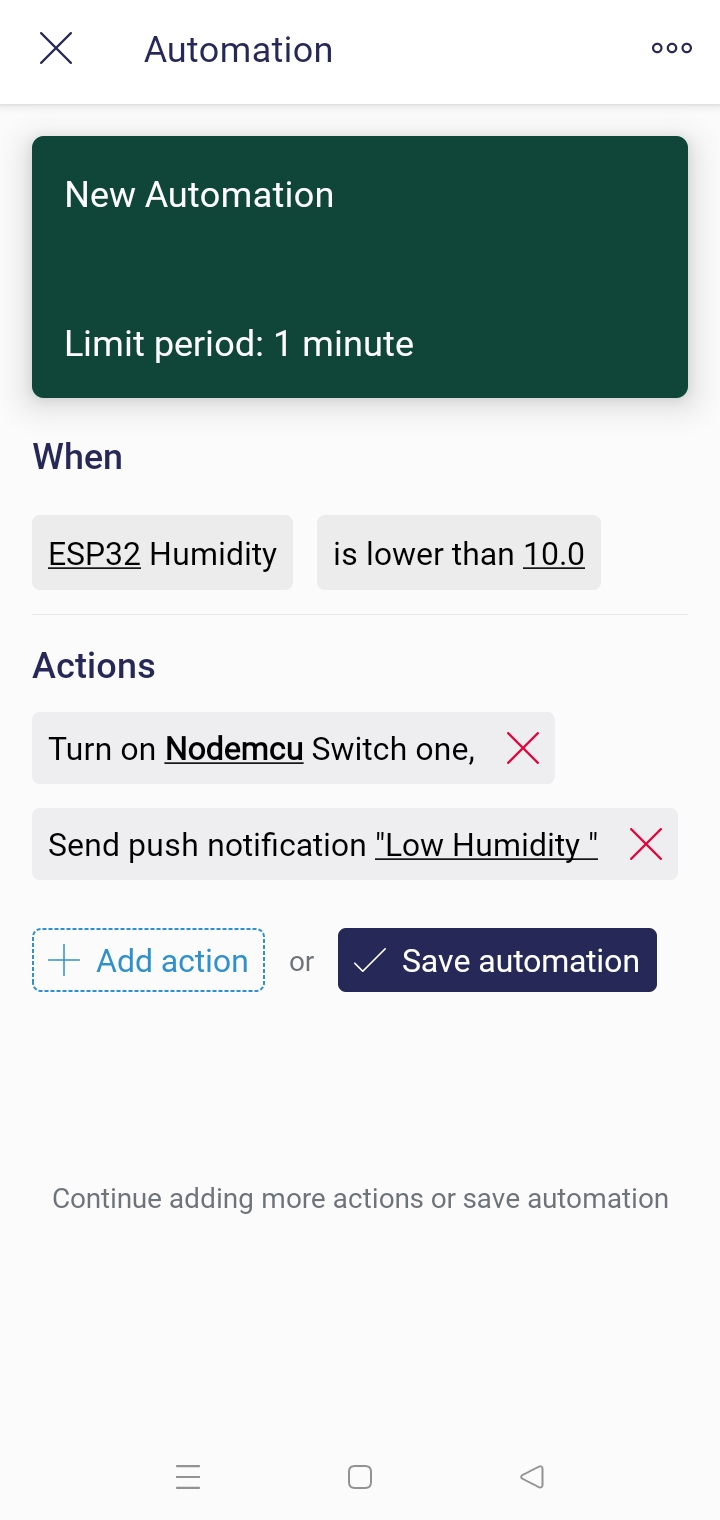
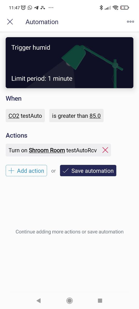
I have created an automation that says “when V1 is greater than 80 than V2 is off”
Both devices are ESP8266.
I hope that clarify my situation, I’m missing the last part of how the relay state is switched.
Thanks for the help.
How did you configure your datastreams ?
Post some screenshots please.
We also need to know what you’ve defined in the automations so far, and where you are running into problems.
But did you do this…
When you create the automation, You’ll obviously start with Device State, and Select Device A
Choose whatever name you’ve assigned to V1, and then define your criteria (Humidity between 75 and 100 maybe).
You’ll then choose Control Device and select Device B, and whatever name you’ve given to datastream V2.
You’ll presumably send a value of 1 to turn the relay on?
What virtual pin handers do you have in your sketch running on Device B to turn the relay on when V2 is set to 1?
Pete.
2 Likes
I can’t add more than one picture so i’ve added in the meantime only the Action configuration:
I guess what confuses me is the demonstration video that states “no code required” and it shows the automation wotking without any code written.
If in the code there is a section that handlers the switching data stream (catches the value 1/0) and applies it to the relay state, than everything makes sense (this is what I understand from this: “What virtual pin handers do you have in your sketch running on Device B to turn the relay on when V2 is set to 1?”).
Thank you.
For any of this information to make sense, you need to translate your “Device A” and “Device B” names into names that match those appearing in your automation screenshot, and state which device each of the datastreams relate to.
You can’t achieve any switching of relays etc using virtual pins without some BLYNK_WRITE(vPin) handler code on your device that has the relay attached to it.
You should read this:
Pete.
Hey Pete, thanks allot for the help!
I now understand that this came from the youtube tutorial on automation’s.
At the end of the tutorial there’s a sentence saying “and no code involved”, and I understood that there
is a way to operate the automation without any code written, I now understand that this is wrong…
Thanks for the patience to explain me how it works.