There seems to quite a bit of confusion about how the dynamic provisioning process works in the Edgent sketch examples, and how to re-provision a device with new WiFi credentials. Many people omit to configure the board type correctly in the sketch, and this also causes problems.
Here’s a guide to how the process works, and the things to watch out for…
Overview
You start by creating a template, preferably in the web console (https://blynk.cloud/)
This gives you the BLYNK_TEMPLATE_ID and BLYNK_DEVICE_NAME that you copy/paste into the Edgent example sketch, replacing the existing lines of code that are commented-out.
To do the Edgent provisioning/reprovisioning process correctly need a physical switch and an LED connected to your board. Some boards have these already, some need to have them added by you. This is covered in detail in the “Defining your physical switch and LED” section below.
In the app you then use the “+ Add New Device” option to connect to the device and supply the WiFi credentials.
The WiFi credentials (and the current Auth token) can be cleared by pressing and holding the physical button for 10 seconds. New WiFi credentials and a new auth token can be provisioned to an existing device using the “Reconfigure” option in the app.
Be careful with the length of your BLYNK_DEVICE_NAME
The Device Name is the name that you provide when you create the template, and the Edgent sketch then adds additional characters that are derived from the Chip ID of the device to give the SSID which is used when the app connects to the device during the provisioning phase.
If the device name + Chip ID exceed 32 characters then the provisioning process won’t complete successfully, so keep the template name to a reasonable length.
Defining your physical switch and LED
This is the area that is probably most confusing to new users of the Edgent sketch, especially if they are unfamiliar with the #define, #if defined, #elif and #endif commands in C++
I’ll use the Edgent_ESP8266 sketch as an example, but the same principals apply to the ESP32 sketch as well.
The Edgent_ESP8266.ino file (the first tab in the Arduino IDE) contains the following lines of code:
// Uncomment your board, or configure a custom board in Settings.h
//#define USE_SPARKFUN_BLYNK_BOARD
//#define USE_NODE_MCU_BOARD
//#define USE_WITTY_CLOUD_BOARD
//#define USE_WEMOS_D1_MINI
Notice that all of these board types are commented-out by default.
Your first task should be to un-comment one of these board types, then look in the Settings.h tab so that you understanhd what the code is doing, and what additional steps you may need to take.
If the board you are using isn’t listed here then leaving all of the board types commented-out will cause the sketch to use the “Custom board configuration” from the Settings.h tab, and you need to edit this custom configuration to suit your hardware.
This is what the relevant parts of the standard Settings.h file look like:
/*
 * Board configuration (see examples below).
 */

#if defined(USE_NODE_MCU_BOARD) || defined(USE_WEMOS_D1_MINI)

  #define BOARD_BUTTON_PIN            0
  #define BOARD_BUTTON_ACTIVE_LOW     true

  #define BOARD_LED_PIN               2
  #define BOARD_LED_INVERSE           true
  #define BOARD_LED_BRIGHTNESS        255

#elif defined(USE_SPARKFUN_BLYNK_BOARD)

  #define BOARD_BUTTON_PIN            0
  #define BOARD_BUTTON_ACTIVE_LOW     true

  #define BOARD_LED_PIN_WS2812        4
  #define BOARD_LED_BRIGHTNESS        64

#elif defined(USE_WITTY_CLOUD_BOARD)

  #define BOARD_BUTTON_PIN            4
  #define BOARD_BUTTON_ACTIVE_LOW     true

  #define BOARD_LED_PIN_R             15
  #define BOARD_LED_PIN_G             12
  #define BOARD_LED_PIN_B             13
  #define BOARD_LED_INVERSE           false
  #define BOARD_LED_BRIGHTNESS        64

#else

  #warning "Custom board configuration is used"

  #define BOARD_BUTTON_PIN            0                     // Pin where user button is attached
  #define BOARD_BUTTON_ACTIVE_LOW     true                  // true if button is "active-low"

  #define BOARD_LED_PIN               4                     // Set LED pin - if you have a single-color LED attached
  //#define BOARD_LED_PIN_R           15                    // Set R,G,B pins - if your LED is PWM RGB
  //#define BOARD_LED_PIN_G           12
  //#define BOARD_LED_PIN_B           13
  //#define BOARD_LED_PIN_WS2812      4                     // Set if your LED is WS2812 RGB
  #define BOARD_LED_INVERSE           false                 // true if LED is common anode, false if common cathode
  #define BOARD_LED_BRIGHTNESS        64                    // 0..255 brightness control

#endif
The first section starts with #if defined(USE_NODE_MCU_BOARD) || defined(USE_WEMOS_D1_MINI)
In plain English this means, “If you’ve uncommented either the #define USE_NODE_MCU_BOARD or #define USE_WEMOS_D1_MINI lines of code in the first tab of the sketch, then the following settings will be used for the physical button and LED”.
The NodeMCU board has 2 physical buttons:
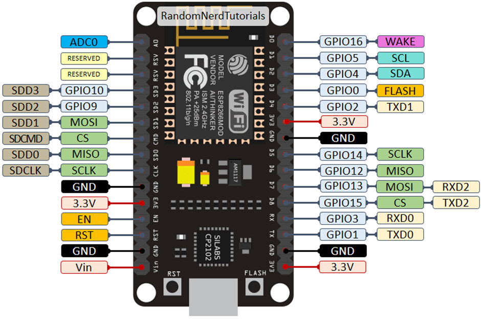
The button on the bottom left is labelled RST and the one on the bottom right is labelled FLASH.
The FLASH button is connected to GPIO0 (the pin labelled D3 on the board). When the button is pressed, GPIO0 is connected to GND (LOW).
All NodeMCUs that I’ve come across also have a built-in LED (located up near the top right of the board) which is connected to GPIO2 (the pin labelled D4). This LED lights-up when GPIO2 is pulled LOW, so has what is known as inverse logic.
Some NodeMCUs also have an additional LED (down near bottom left of the board) which is connected to GPIO16 (The pin labelled D0). This LED also works in “Inverted” mode – it lights-up when the pin is pulled LOW.
Going back to the standard settings for the NodeMCU/Wemos D1 Mini board, you should now understand these settings in relation to the board, but I’ve added some comments next to each line to explain them further…
#if defined(USE_NODE_MCU_BOARD) || defined(USE_WEMOS_D1_MINI)

  #define BOARD_BUTTON_PIN            0      <<<< The FLASH Button
  #define BOARD_BUTTON_ACTIVE_LOW     true   <<<< Pressing the button pulls the pin LOW

  #define BOARD_LED_PIN               2      <<<< The LED is connected to GPIO2 (D4)
  #define BOARD_LED_INVERSE           true   <<<< The LED lights when the pin is LOW
  #define BOARD_LED_BRIGHTNESS        255    <<<< Make the LED shine at max brightness when lit
If you’re using the Wemos D1 mini, it is very similar:
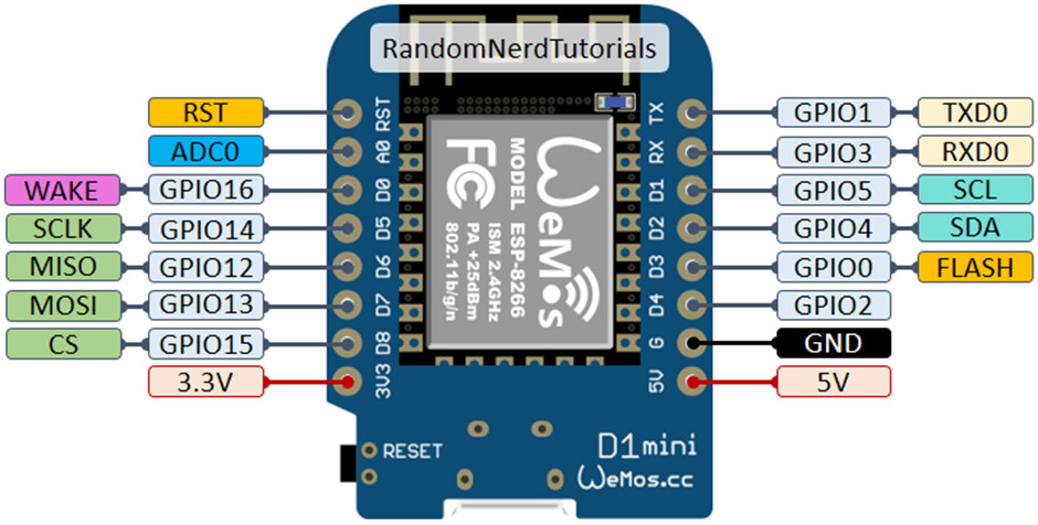
but you’ll notice that it only has one button labelled RESET (same as the RST button on the NodeMCU).
It doesn’t have the FLASH button, so you’ll need to add a physical momentary push to make button in order to be able to clear the stored credentials if ever you need to re-provision the board.
One side of the physical push button will connect to the pin labelled D3 and the other side to GND (because we have this line set to true:
#define BOARD_BUTTON_ACTIVE_LOW true
which means that when the button is pressed the GPIO0 (D3) pin is pulled LOW).
Of course, if you wanted to, you could simply use a jumper wire, bent paperclip or anything else that’s conductive to short-out pin D3 and GND for 10 seconds if you are feeling lazy 
So, if you don’t un-comment one of the pre-defined board types, the custom board type configuration will be used. That looks like this:
  #warning "Custom board configuration is used"

  #define BOARD_BUTTON_PIN            0                     // Pin where user button is attached
  #define BOARD_BUTTON_ACTIVE_LOW     true                  // true if button is "active-low"

  #define BOARD_LED_PIN               4                     // Set LED pin - if you have a single-color LED attached
  //#define BOARD_LED_PIN_R           15                    // Set R,G,B pins - if your LED is PWM RGB
  //#define BOARD_LED_PIN_G           12
  //#define BOARD_LED_PIN_B           13
  //#define BOARD_LED_PIN_WS2812      4                     // Set if your LED is WS2812 RGB
  #define BOARD_LED_INVERSE           false                 // true if LED is common anode, false if common cathode
  #define BOARD_LED_BRIGHTNESS        64                    // 0..255 brightness control
As you can see, this uses GPIO0 (Pin D3) for the physical pushbutton switch, but GPIO4 (pin D2) for the LED. It also has the option to un-comment additional lines of code that allow an RGB or WS2812 RGB LED to be used.
If you didn’t un-comment any board types, and allowed the custom board configuration to be used, then with a NodeMCU the built-in LED wouldn’t flash to indicate provisioning or pulse to indicate normal running. But, pin GPIO4 would still be receiving these pulses from the sketch, and if you had a sensor or relay attached to GPIO4 then this could provide unexpected results.
So, the important points are:
-
Un-comment the correct board type
-
Check the Settings.h file to ensure that the selected board type does actually match your hardware setup
-
Add a physical button to the Wemos D1 mini if needed
-
Use the custom board configuration of you have an unusual type of board, but edit the custom section of Settinsg.h to make it match your hardware.
-
Ensure that you don’t use the GPIOs assigned to the button or LED pins for anything else in your sketch.
Initial Provisioning
Once you’ve added the BLYNK_TEMPLATE_ID and BLYNK_DEVICE_NAME to your sketch, configured the correct board type and uploaded the sketch to your board you are ready to do the provisioning.
It’s always a good idea to have the board connected to your computer and the serial monitor open, so that you can see the debug information that’s being provided in the serial output.
The LED on the board should be flashing quickly.
Open the app and tap the three horizontal bars in the top right-hand corner then tap “+ Add new device”. Choose “Connect to WiFi” and confirm that the device is ready to be provisioned (LED blinking) by tapping “Ready” in the app.
The app will then scan for devices waiting to be provisioned, and show you the device details and ask for permission to join the network (select Join), then ask you to select the SSID and enter the WiFi password.
Once you’ve done this the data is sent to the device and stored in it’s EEPROM, and you can exit the “Add device" when asked (Apply, Done, Exit to App).
The device will then appear in the initial screen of the app, ready to have widgets added to its mobile dashboard.
Troubleshooting the provisioning process
If the LED on the board isn’t doing anything, then go back and check the “Defining your physical switch and LED” section to ensure that the LED and switch are defined correctly, and that you don’t have any peripherals also using the LED or Switch pins.
If the LED is pulsing slowly then the board thinks it’s already provisioned. Follow the instructions in the “Reprovisioning new WiFi credentials” section below.
If the LED is flashing quickly, but the device doesn’t show-up in the app when you tap the “Ready” button in the app then check the following:
- The Template name isn’t too long (see the “Be careful with the length of your BLYNK_DEVICE_NAME” section above)
- The template ID and device name in sketch are EXACTLY as they appear in the web console
- The app is signed-in to the same user account as the web console, or
- The user has permission to provision new devices.
Reprovisioning new WiFi credentials
If you’re having problems provisioning a device, or you’ve accidentally entered the wrong WiFi credentials, then press and hold the physical button (the one defined in Settings.h for your board type) for 10 seconds. This will clear the stored credentials and te LED will start flashing quickly, and allow you to either repeat the provisioning process, or if the device has already been created in the app you can re-provision it.
To re-provision an existing device, tap on the device in the app, then tap the three dots in the top right hand corner of the app screen. This will bring-up the device information/timeline screen.
Tap on the three dots in the top right hand corner once more, and this will pop-up a dialog that allows you to “Reconfigure”, “Erase all device data”, “Delete Device” or “Cancel”.
Choose “Reconfigure” and this will take you back into the provisioning process described in the earlier section.
If the wrong SSID was selected and/or the password was entered before then take care to enter the correct information rather than using the credentials stored in the app.
PLEASE - Don’t post general provisioning questions in this topic
I’ll leave this topic open for constructive comments, as I’d like to know if there are any mistakes, ambiguities or important areas that I’ve forgotten to cover - or if the process is different in any way when using the Android app (I’m an iOS user).
However, I’d like the topic to be a simple reference for others to follow, so don’t want it to be cluttered-up with “I get this error message, please help me” type of comments. If you post these types of comments then they will simply deleted.
Pete.
 your talent is needed to improve our docs! Would you consider?