• Hardware model: esp8266 nodemcu 3.0 and ESPWROOM32S - SERIAL AND WIFI CONEXION ON BLYNKEDGENT
• ANDROID 12 SMARTPHONE - WINDOWS 10-11 PC
• BLYNK SERVER
• LAST LIBRARY BLYNK VERSION
I need initial help, I have a project that I have been using with ESP8266, and it works well, but I want to start using it with ESP32, since I have run out of ports for sensors that I use and I have also read other good features that it has. The question is that I don’t know which library the board I bought specifically uses and I don’t know how to start BlynkEdgent (which of the options in the example to choose), I already know that I have to have the button pressed to load the script and I could load some. If you guide me I would appreciate it.
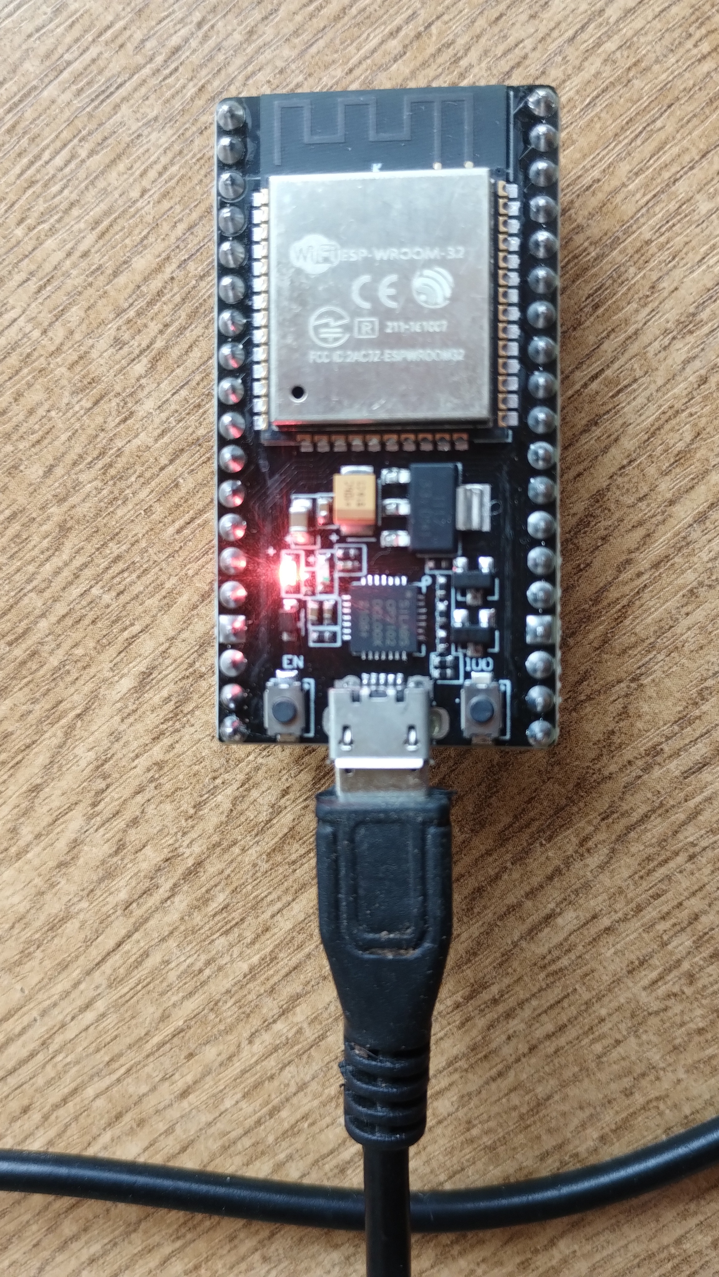
The board is an ESPWROOM32s v1.1 101010 211-10107 - SILABS CP2102 chip.
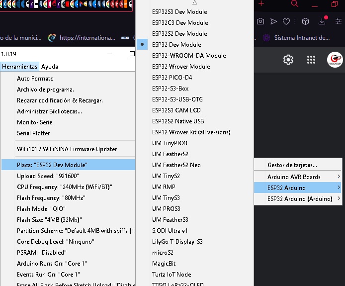
The libraries that appear when I load a link that I found in a forum are shown in this image:
These are board definitions in the ESP32 core, not libraries.
A Google search for “ ESPWROOM32s v1.1 101010 211-10107 - SILABS CP2102” returns no results.
As far as the board types in the Edgent example are concerned, these are use to select a group of options in the Settings.h tab of the Edgent example.
This defines which pin you have your indicator LED attached to, and which pin is going to have a physical button attached to it to clear the stored WiFi credentials and Auth token. The options also allow you to define if the LED and button are active HIGH or LOW.
If your board has an onboard LED that is attached to a GPIO then this can be used as your indicator. If not then you could add an LED with a current limiting resistor to a suitable pin of your choice.
If your board has a spare onboard button (not the RST button) then this could be used as your “clear credentials” button.
If not then you could add a button to a suitable pin of your choice.
You might find this topic helpful if you need more info…
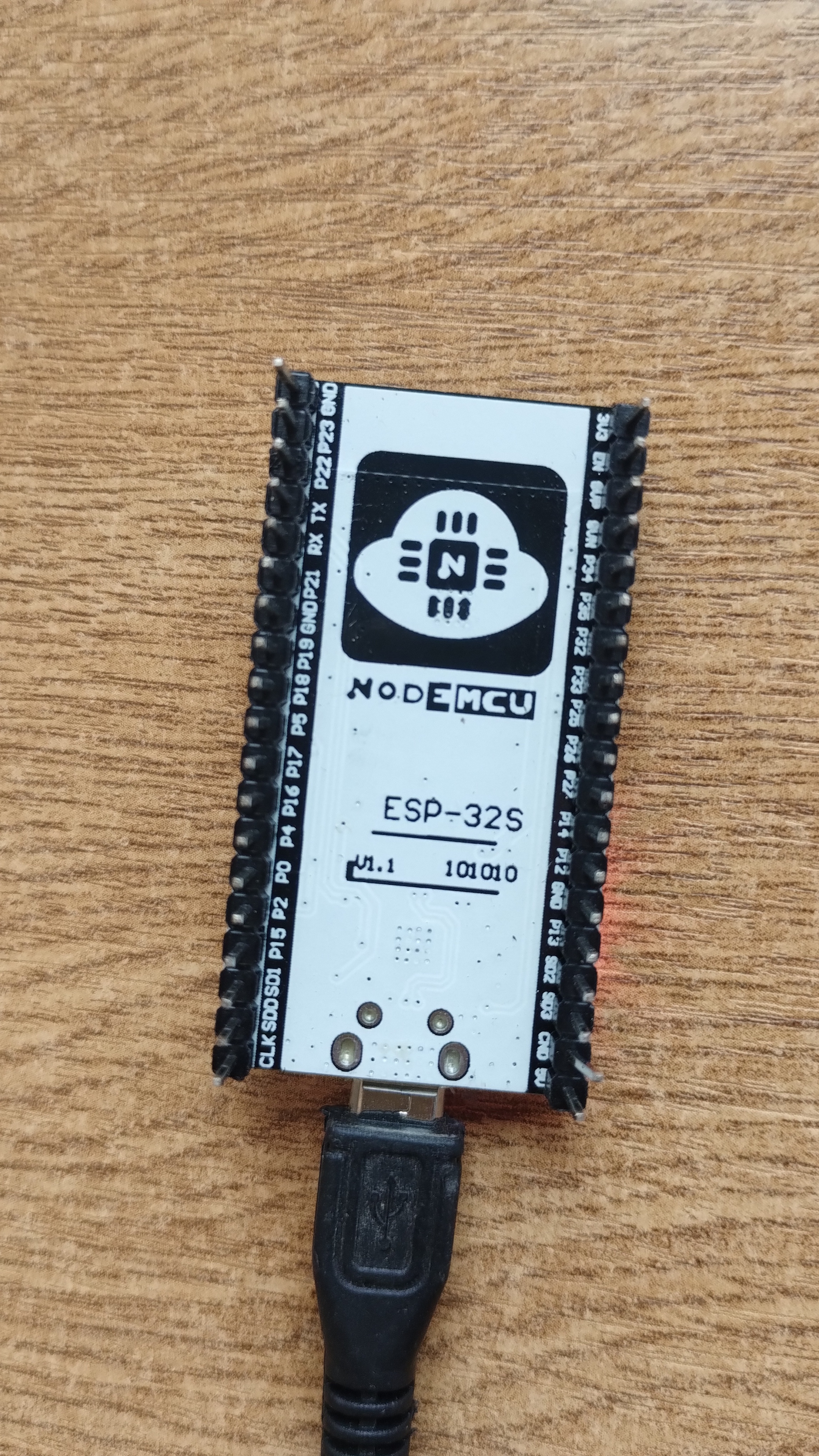
Thanks Pete, I can always count on you. I started searching further by photo and found the description of the Nodemcu, I just need to know which are the correct pins and how to configure the BlynkEdgent example. The problem is that I still don’t know if I am using the correct library in Arduino. This I found:
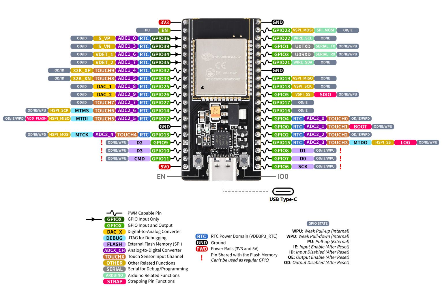
The button on the bottom right is connected to GPIO0 and according to the schematic the pin will be pulled LOW when the button is pressed.
The blue LED is connected to GPIO2 and according to the schematic for the board it will be lit when the pin is HIGH
Once again, this is not a library.
It’s a board type, and choosing the ESP32 Dev Board type as shown in your initial post will be fine.
In the Edgent sketch you need to look at the existing board definitions and find one that is close to the GPIOs for your board, and tweak it if necessary, or use the default Custom board definition and amend it to suit your board.
This will all make sense if you’ve read the link I provided.
Thanks Pete, reading what you posted I understood how to use setting.h and be able to customize it to be compatible with my board. I would only need to turn off the red LED when connecting to Blynk like the ESP8266 does. It looked like this:
#warning "Custom board configuration is used"

  #define BOARD_BUTTON_PIN            0                     // Pin where user button is attached
  #define BOARD_BUTTON_ACTIVE_LOW     true                  // true if button is "active-low"

  #define BOARD_LED_PIN             2                     // Set LED pin - if you have a single-color LED attached
  //#define BOARD_LED_PIN_R           15                    // Set R,G,B pins - if your LED is PWM RGB
  //#define BOARD_LED_PIN_G           12
  //#define BOARD_LED_PIN_B           13
  //#define BOARD_LED_PIN_WS2812      4                     // Set if your LED is WS2812 RGB
  #define BOARD_LED_INVERSE           false                 // true if LED is common anode, false if common cathode
  #define BOARD_LED_BRIGHTNESS        64                    // 0..255 brightness control

#endif