A post was split to a new topic: How to repeat the same activity or stop the activity form a function that is called by a BLYNK_WRITE(V?) function
#19 - Modified Text Input Widget performance - Now with 100% more line feed 
Well, here is another modification to make a widget work how I at least think it could (and possibly temporary… see my supplanted multi-coloured button above  )
)
NOTE: This is NOT intended to undermine what Blynk has made… just add in my own personal preferences to somthing I wish to use in a particular way.
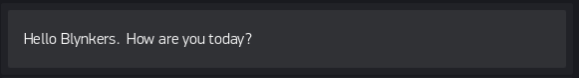
The text Input widget is great… easy to use and compact, compared to the Terminal input option. Only one thing… It doesn’t act like a ‘true’ (IMHO) text input. No EOL, ‘carriage return’ or clearing upon hitting return. All by design? Perhaps 
Well, here is my simple code mod to supply all those “missing” features 
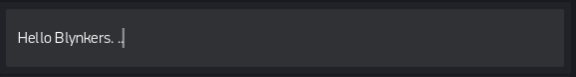
You can still use the Widget as intended, or with the addition of a space and two periods (customisable) followed by the return key. you can get a cleared widget and a new line in the resulting string.
Due to the need for a SPACE to “clear” the widget… some post processing is used to remove a single leading SPACE from your string, if present.
String textIn; // declare global variable

//===== Modified Text Input Widget - BLYNK Function =====
BLYNK_WRITE(V0) {
  String textIn = param.asStr(); // Get string from Text Input Widget
  if (textIn.startsWith(" ")) {  // If it has a leading SPACE...
    textIn.remove(0, 1);  // ...remove it.
  }
  if (textIn.endsWith(" ..")) {  // If it has customisable EOL indicator, In my case SPACE and 2 PERIODS...
    textIn.replace(" ..", "\n"); // ...replace with newline command
    Blynk.virtualWrite(V0, " ");  // "clear" the Text Input field.  A null "" will not work, so needs a space
  }
  Serial.print(textIn);  // Show string output as intended, or do whatever you want with the string.
  Blynk.virtualWrite(vPin, textIn);  // Like send it to a terminal Widget
}
So if you want or need a truer text entry feeling, with carriage return effects… this…
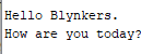
…can become this, just by ending with a SPACE and 2 PERIODS (customisable)


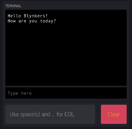
To give this output…
And for the fun of it, here is some code to add a Clear Terminal button.
//===== Clear Terminal Widget =====
BLYNK_WRITE(vPin) {  // Button Widget
  if (param.asInt()) {
    Blynk.virtualWrite(vPin, "clr");  // Clears terminal if button state is 1
  }
}
3 Likes
#20 - Variable timer
There has been a few discussions about how to vary the interval time of a timer… I have even used one way in an earlier post above with the adjustable servo sweep.
But here is an easier way… use a one-shot Timeout Timer instead…
Create your function that you want to run on a variable interval, but don’t call that function with an outside timer, just call it the first time (if you want) in your setup or upon Blynk connect, or even wait until you chose a time, etc.
Then, using a global variable acquired from some other source (Slider, Step Control, Numeric input, etc.) end your custom timed function with a timeout timer, set to the required variable, that calls the same function it is already in.
If you really want to get fancy, you can setup Timer IDs and run a delete timer at the beginning of the function, thus allowing you to interrupt and cancel whatever previous setting… preventing duplicate function runs from leftover timeout timers.
long variableTime = 1000; // default interval time of 1 second
int varTimer;  // Setup Timeout Timer ID
BLYNK_WRITE(V0) { // Widget for interval timing
  variableTime = param.asInt();
  if (variableTime <= 0) { // prevents a timer from becoming 0 or less
    variableTime = 1;
  }
  timerLoop();  // Call your timed loop
}


void timerLoop() {
  timer.deleteTimer(varTimer);  // Cancel previous Timeout Timer
  //
  //  Do your stuff here every (variableTime) seconds
  //
  varTimer = timer.setTimeout(variableTime, timerLoop);  // Set new Timeout timer
}
9 Likes
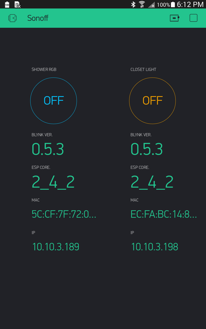
#21 - Sonoff Basic - Blynk and physical button control - with LED (showing ON status), OTA and displaying device specifics.
This is just a simple sketch for a Blynkified Sonoff Basic. Use either App or physical button to toggle the Sonoff. Physical button works even if no Server connected.
/*
   Sonoff Basic
   1MB (No SPIFS) flash size
   115200 BAUD
   MUST USE DOUT for Flash Mode!!

   sonoff header
   1 - vcc 3v3
   2 - rx
   3 - tx
   4 - gnd
   5 - gpio 14

   esp8266 connections
   gpio  0 - button
   gpio 12 - relay
   gpio 13 - green led - active low
   gpio 14 - pin 5 on header
*/

#include <ESP8266WiFi.h>  // for ESP8266
#include <BlynkSimpleEsp8266.h>  // for ESP8266
#include <ESP8266mDNS.h>  // For OTA w/ ESP8266
#include <WiFiUdp.h>  // For OTA
#include <ArduinoOTA.h>  // For OTA

char auth[] = "xxxxxxxxxx";  // Sonoff
char ssid[] = "xxxxx";
char pass[] = "xxxxx";
char server[] = "xxx.xxx.xxx.xxx";  // IP for your Local Server
int port = 8080;

int pinState = LOW;
int btnState = HIGH;

BlynkTimer timer;
void PhysButton();

void setup() {
  pinMode(0, INPUT);
  pinMode(12, OUTPUT);
  pinMode(13, OUTPUT);
  digitalWrite(13, HIGH);  // Turn OFF LED

  timer.setInterval(250L, PhysButton);  // scan for physical button press

  WiFi.begin(ssid, pass);
  Blynk.config(auth, server, port);
  Blynk.connect();

  ArduinoOTA.setHostname("Sonoff");  // For OTA - Use your own device identifying name
  ArduinoOTA.begin();  // For OTA
}


void loop() {
  Blynk.run();
  timer.run();
  ArduinoOTA.handle();  // For OTA
}


BLYNK_CONNECTED() {
  Blynk.syncVirtual(V0);
  Blynk.virtualWrite(V1, BLYNK_VERSION);
  Blynk.virtualWrite(V2, ESP.getCoreVersion());
  Blynk.virtualWrite(V3, WiFi.macAddress());
  Blynk.virtualWrite(V4, WiFi.localIP().toString());
}


BLYNK_WRITE(V0) { // Button Widget in switch mode
  digitalWrite(12, param.asInt());  // Toggle relay
  digitalWrite(13, !param.asInt());  // Toggle LED
}

void PhysButton() {
  if (digitalRead(0) == LOW) {
    // btnState is used to avoid sequential toggles
    if (btnState != LOW) {

      // Toggle LED state
      pinState = !pinState;
      digitalWrite(12, pinState);
      digitalWrite(13, !pinState);  // Toggle LED

      // Update Button Widget
      Blynk.virtualWrite(V0, pinState);
    }
    btnState = LOW;
  } else {
    btnState = HIGH;
  }
}
My simple display used to fit everything the way I wanted (centered columns under the buttons)… but now it looks lopsided with extended displays, that still crop on some devices… Boo!! Hiss!!

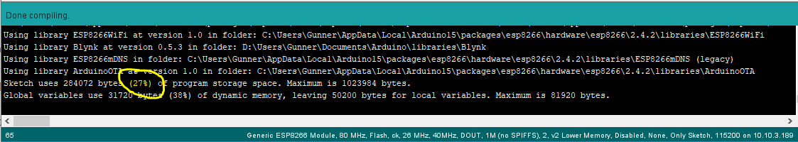
The sketch fits on the Sonoff, with a bit of room for more code 
9 Likes
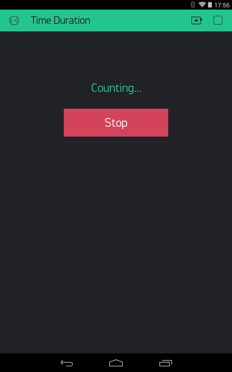
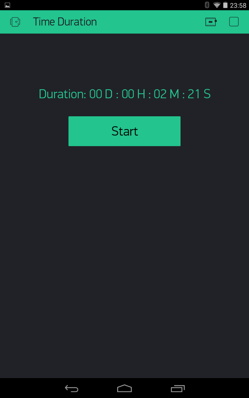
#22 - Super Simple Duration Counter
OK, 'fess up time… I have rarely used millis() unless it was already included in some example or snippet copied from elsewhere, so I just assumed using it for actual human readable time was difficult… Well, it is not!! 
V0 is a Button Widget set to switch mode
V1 is a Display Widget
And that is it… If all you need is a readable Hours/Minutes/Seconds duration display, without using Time library, RTC, etc. then here you go.
EDIT - Updated to count days as well, should your MCU stay running without reset that long 
You can take the key commands & process and implement them in any other type of displayable duration routine you want.
int runDays;
int runHours;
int secsRemaining;
int runMinutes;
int runSeconds;
char buf[21];
unsigned long startMillis;
unsigned long endMillis;
unsigned long allSeconds;


BLYNK_WRITE(V0) { // Switch Widget
  if (param.asInt() == 1) {
    startMillis = millis();  // The key command for starting the count
    Blynk.virtualWrite(V1, "Counting...");  // Display Widget
  } else {
    endMillis = millis();  // The key command for ending the count

    // The key process for displaying the converted duration
    allSeconds = (endMillis - startMillis) / 1000;
    runDays = allSeconds / 86400;
    secsRemaining = allSeconds % 86400;
    runHours = secsRemaining / 3600;
    secsRemaining = allSeconds % 3600;
    runMinutes = secsRemaining / 60;
    runSeconds = secsRemaining % 60;
    sprintf(buf, "Duration: %02d D : %02d H : %02d M : %02d S", runDays, runHours, runMinutes, runSeconds);
    Blynk.virtualWrite(V1, buf);  // Display Widget showing duration the Switch was
  }
}
8 Likes
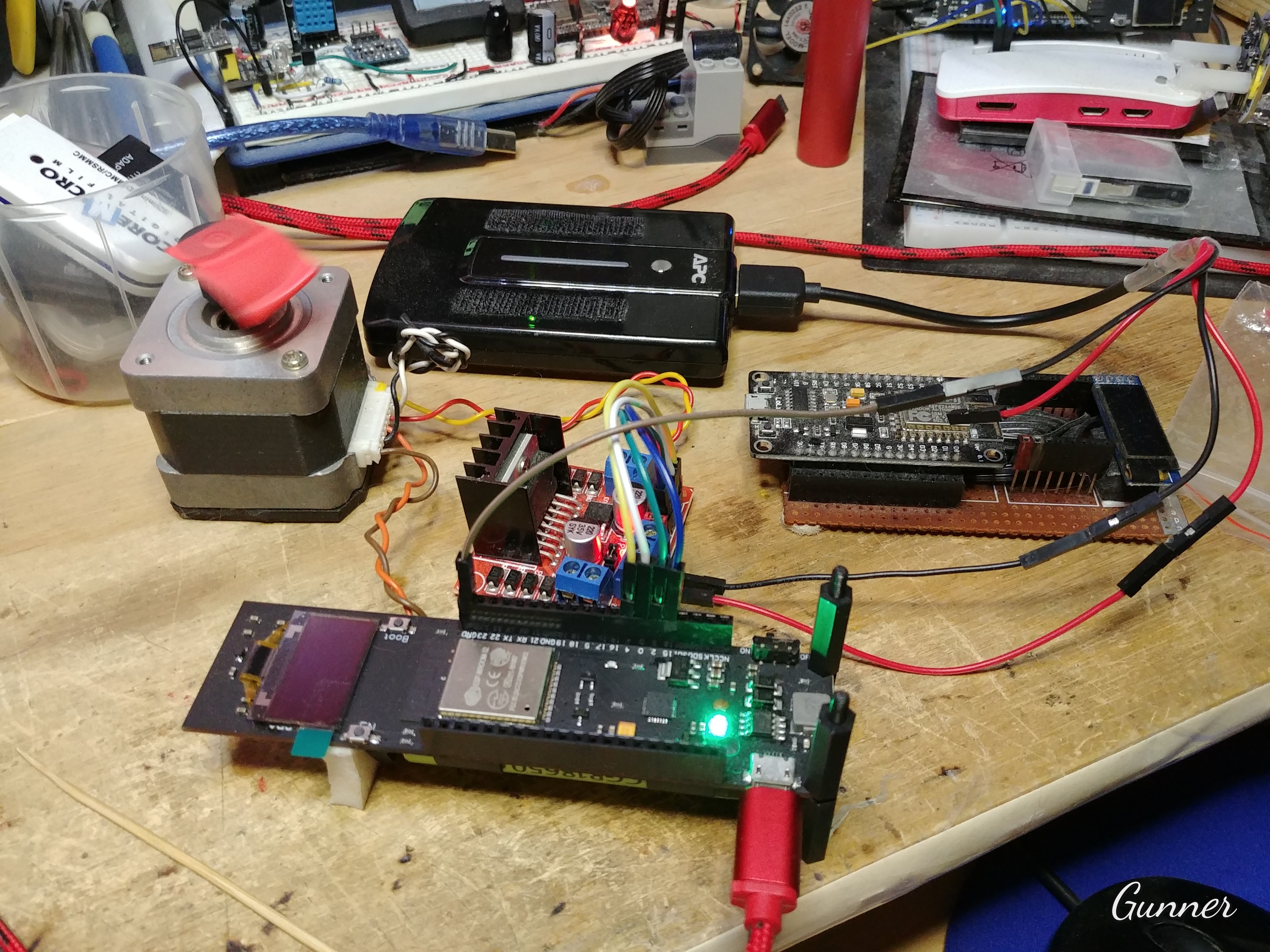
#23 - Basic Stepper Motor Control
Who says Blynk can’t control Stepper motors… well, OK, I have said it may require fancy non-blocking timing… so here it is (disclaimer, not all that fancy after all )
Yes, it is using the old and decrepit Stepper.h library… only because I was too lazy to learn simple accelStepper commands at this moment
I am also controlling a 4.29v 1.8deg NEMA 17 stepper with an equally old L298D motor controller… Hey, I works with what I gots 
UPDATE - Chose the commented out commands for ESP8266 (default) or ESP32, both with OTA (no I haven’t mastered #ifndef yet )
Uses a Slider Widget for speed - Slider V0 set with 0-100 and Send On Release ON (But if you really want it OFF, preferably at around 300-500ms, so you don’t flood the connection unnecessarily).
And a Button Widget for direction - Button V1 set as Switch with 0-1
#define BLYNK_PRINT Serial // This prints to Serial Monitor
//#define BLYNK_DEBUG  // Optional, this enables more detailed prints

////  Pick one Blynk Device Library group or other
////----------
// #include <WiFi.h>  // for ESP32
// #include <WiFiClient.h>  // for ESP32
// #include <BlynkSimpleEsp32.h>  // for ESP32
////----------
#include <ESP8266WiFi.h>  // for ESP8266
#include <BlynkSimpleEsp8266.h>  // for ESP8266
////----------

////  Pick one OTA Library or other
////----------
// #include <ESPmDNS.h>  // For OTA w/ ESP32
////----------
#include <ESP8266mDNS.h>  // For OTA w/ ESP8266
////----------

#include <WiFiUdp.h>  // For OTA
#include <ArduinoOTA.h>  // For OTA

char auth[] = "xxxxxxxxxx";
char ssid[] = "xxxxx";
char pass[] = "xxxxx";
//char server[] = "xxx.xxx.xxx.xxx";  // IP for your Local Server
char server[] = "blynk-cloud.com";  // URL for Blynk Cloud Server
int port = 8080;

BlynkTimer timer;

#include <Stepper.h>
const int stepsPerRevolution = 200;  // change this to fit the number of steps per revolution for your motor

// ESP8266 use GPIO pin designation, not silk-screened labeling
Stepper myStepper(stepsPerRevolution, 5, 4, 0, 2); // ESP8266 - initialize the stepper library for IN1, IN2, IN3, IN4

// ESP32 GPIO/Silk-screened pin designation
//Stepper myStepper(stepsPerRevolution, 15,2,0,4); // ESP32 - initialize the stepper library for IN1, IN2, IN3, IN4

int motorSpeed;
int motorDirection;


void setup() {
  Serial.begin(9600);

  timer.setInterval(10, stepperControl);  // This here is all the fancy timing part... it just updates the stepper control every 5ms

  WiFi.begin(ssid, pass);
  Blynk.config(auth, server, port);
  Blynk.connect();

  ArduinoOTA.setHostname("ESP Blynk Stepper");  // For OTA - Use your own device identifying name
  ArduinoOTA.begin();  // For OTA
}


void loop() {
  Blynk.run();
  timer.run();
  ArduinoOTA.handle();  // For OTA
}


BLYNK_CONNECTED() {
  Blynk.syncVirtual(V0, V1);
}

BLYNK_WRITE(V0) {  // Motor Speed - Slider set with 0-100 and Send On Relese OFF
  motorSpeed = param.asInt();
  myStepper.setSpeed(motorSpeed);
}

BLYNK_WRITE(V1) {  // Motor Direction - Button set as Switch with 0-1
  motorDirection = param.asInt();
}


void stepperControl() {
  if (motorSpeed > 0) {
    if (motorDirection == 0) {  // Rotate Clockwise
      myStepper.step(stepsPerRevolution / 100);
    } else {  // Rotate CounterClockwise
      myStepper.step(-stepsPerRevolution / 100);
    }
  }
}
7 Likes
#24 - Timed Button Widget
Just cuz it keeps getting asked for  It is an improved & simplified version of my Latch & indicator example in my #12 - Timers Simplified post above.
Set your vPin, dPin and timeout accordingly… And exchange the digitalWrite() for whatever you want to happen for the timed duration
int latchButton;
int latchFlag;

//===== Timeed latching button =====
BLYNK_WRITE(vPin) {  // Button Widget set as switch
  latchButton = param.asInt();
  if (latchButton == 1 && latchFlag == 0) {
    latchFlag = 1;  // Keeps from allowing button press more then once while relay activated
    // ----- Start your timed thing here
    digitalWrite(dPin, HIGH); // Activate digital pin
    // -----
    timer.setTimeout(5000L, []() {  // Timed Lambda Function - Latching Button release after 5 seconds
      // ----- Stop your timed thing here
      digitalWrite(dPin, LOW); // Deactivate digital pin
      // -----
      Blynk.virtualWrite(vPin, 0);  // Reset Latching Button to OFF
      latchFlag = 0;  // resets to allow next interaction
    });  // END Timer Function
  } else {
    if (latchButton == 0 && latchFlag == 1) {  // If you try to tun off the button before time is up
      Blynk.virtualWrite(vPin, 1);  // Restore Latching Button ON until timer is finished
    }
  }
}
If you add in timer ID and some different } else { coding you can make the timer reset if you turn OFF the button before the timer is finished.
If you do nothing in the ON mode and only activate your “thing” once the timeout occurs, you can call this a delayed reaction button… a little more code and you can make it so you MUST hold the button for the timeout to occur
But for now I will leave all that experimenting to you
6 Likes
#25 - Das Timed Blinkin’ LED… Without any delay() - AKA Timerception 

This is simply just two nested Lambda functions using BlynkTimer and two different timer types to flash a Virtual LED ON for 1 second and Off for 1 second… If this is placed in the void setup() it just repeats in the background… marquee style.
Here it is integrated into a bare bones Blynk Blink Sketch… There should be enough commenting to figure it out from here. LED Widget set to V0
#include <ESP8266WiFi.h>  // for ESP8266
#include <BlynkSimpleEsp8266.h>  // for ESP8266
#define BLYNK_MSG_LIMIT 0  // In theory this disables the "anti-flood governor"... might only work on Local Server

BlynkTimer timer;

char auth[] = "xxxxxxxxxx";  // Auth Token
char ssid[] = "xxxxxxxxxx";  // Your WiFi network name
char pass[] = "xxxxxxxxxx";  // Your WiFi network password
char server[] = "blynk-cloud.com";  // Cloud Server address
int port = 8080;  //  MCU Hardware Device port


void setup() {
  pinMode(2, OUTPUT);  // Setup GPIO2 (D4 the ESP On-Board LED) as an output pin

  // Connect to your WiFi network, then to the Blynk Server
  WiFi.begin(ssid, pass);
  Blynk.config(auth, server, port);
  Blynk.connect();

  // This dual nested timer routine will constantly blink both a Virtual LED and the onboard LED of an ESP8266 Dev Board
  timer.setInterval(2000L, []() {  // Start 1st Timed Lambda Function - Turn ON LED every 2 seconds (repeating)
    timer.setTimeout(1000L, []() {  // Start 2nd Timed Lambda Function - Turn OFF LED 1 second later (once per loop)
      Blynk.virtualWrite(V0, 0);  // Turn Virtual LED OFF
      digitalWrite(2, HIGH); // Turn ESP On-Board LED OFF
    });  // END 2nd Timer Function
    Blynk.virtualWrite(V0, 255);  // Turn Virtual LED ON
    digitalWrite(2, LOW); // Turn ESP On-Board LED ON
  });  // END 1st Timer Function
}


void loop() {
  Blynk.run();
  timer.run();
}
So… why…?
Well I have heard that it is too complicated to make or understand the code to blink an LED without using delay() You be the judge
Also, because it is a nice, non-blocking (payload depending), simple package of code that can be used to repeatedly do just about anything you want, as many times as you need (E.g. replace the first setInterval() timer with a setTimer() and designate your total loops to run. See - timer.setTimer()
Challenge - I am nesting only two functions here… How many nested lambda timed functions can you make use of? Either for practical or just visual purposes.
8 Likes
#26 - Adjustable pulsing LED that fades in and out with Timers
And now for more Timerception tricks… A variable timed, flashing (pulsing) physical LED that fades in and out, all with nested timers in lambda functions.
One of the lambda tricks I had to discover, via trial and error, was using a “fixed call” interval timer called simply setTimer(long d, timer_callback f, int n) that will run its timed interval course as normal, but only n many times before stopping… the key was finding where to put the integer n in a Lambda.
Note the necessary preceding comma…
int timer.setTimer(long d, []() {
  // your code in lew of timer_callback f
}, int n);
AKA
timerId = timer.setTimer(1000L, []() {
// Repeat me every second but only five times
}, 5);
Another glitch in SimpleTimer (of which BlynkTimer is based) is that when using timer ID labels, needed to do things like disable, enable, delete, etc. timers, it seems like the first timer in your code will also get ‘deleted’… I found making your first timer a simple “Sacrificial Timer” that solves that little issue 
  // "Sacrificial" Timer - needed when deleting timers as using that feature will also kill first timer created...
  timer.setTimeout(10L, []() {
    // do nothing here, or some other task that needs only run once EG. Blynk.virtualWrite(V0, "START");
  });  // END sacrificial Function
In this example each chosen interval time, measured in quarter “seconds” (measured in binary units of 256, starting at 512 for shortest setting - all due to the math) will result in half that time fading up and the other half fading down. The longer the total duration, the slower the fade will appear.
Due to the fast pace of the active fade count and analogWrite() from 0-255-0, there will be timing constraints needed to mimic this with a virtual LED… Perhaps I will figure that out later  - EDIT See something like this here
- Display Widget on V0 for uptime in seconds
- Built in LED (GPIO2) on NodeMCU and Wemos will blink as a “sign of life” indicator.
- Display Widget on V1 for current interval value
- Button Widget V2 for changing the interval
- Physical button bringing GPIO0 to GND will “sync” with virtual button… and thus you can control this without Server connection.
#define BLYNK_PRINT Serial
#include <ESP8266WiFi.h>
#include <BlynkSimpleEsp8266.h>

char auth[] = "xxxxxxxxxx";
char ssid[] = "xxxxxxxxxx";
char pass[] = "xxxxxxxxxx";
//char server[] = "xxx.xxx.xxx.xxx";  // IP for Local Server
char server[] = "blynk-cloud.com";  // IP for Cloud Server
int port = 8080;

int i;  // PWM count ID
int fadeUP;  // Timer ID
int fadeDOWN;  // Timer ID
int countUP;  // Timer ID
int countDOWN;  // Timer ID
int pulseTime = 256;  // Initial interval, not valid until incremented, else causes divide error
int btnState = HIGH; // Flag
int VbtnPin = LOW; // Flag
int buttonBlock = LOW; // Flag
const int btnPin = 0;  // Pin ID
const int ledPin = 14;  // Pin ID
const int builtinledPin = 2;  // Pin ID

BlynkTimer timer;


void setup() {
  Serial.begin(9600);  // BLYNK_PRINT data
  pinMode(btnPin, INPUT);
  pinMode(builtinledPin, OUTPUT);
  pinMode(ledPin, OUTPUT);

  WiFi.begin(ssid, pass);  // Connect to WiFi
  Blynk.config(auth, server, port);
  Blynk.connect();  // Initialise Connection to Server

  // "Sacrificial" Timer - needed when deleting timers as using that feature will also kill first timer created...
  timer.setTimeout(10L, []() {
    Blynk.virtualWrite(V0, "START");
  });  // END sacrificial Function

  // Timed Lambda Function - UpTime & Heartbeat...
  timer.setInterval(1000L, []() { // Run every second
    Blynk.virtualWrite(V0, millis() / 1000);  // Display the UpTime in seconds
    digitalWrite(builtinledPin, !digitalRead(builtinledPin));  // For "heartbeat" indicator on device
  });  // END UpTime Function

  // Timed Button watcher...
  timer.setInterval(100L, buttonScan);
}


BLYNK_CONNECTED() {
Blynk.virtualWrite(V1, "OFF");  // display the pulse interval as OFF
}


void loop() {
  Blynk.run();
  timer.run();
}


void buttonScan() {  // Change interval time via Physical Button
  if (digitalRead(btnPin) == LOW || VbtnPin == HIGH && buttonBlock == LOW) {
    if (btnState != LOW) {  // btnState is used to avoid sequential toggles
      timer.deleteTimer(fadeUP);  // Stop Timer
      timer.deleteTimer(fadeDOWN);  // Stop Timer
      timer.deleteTimer(countUP);  // Stop Timer
      timer.deleteTimer(countDOWN);  // Stop Timer
      pulseTime += 256;  // Increment pulse interval
      if (pulseTime > 5120) {  // Loop the pulse interval time back to the beginning
        pulseTime = 256;
        Blynk.virtualWrite(V1, "OFF");  // display the pulse interval as OFF
        analogWrite(ledPin, 0);  // Turn off LED
        return;
      }
      Blynk.virtualWrite(V1, pulseTime);  // display the pulse interval
      fadeLEDFunction();  // Start the pulsed fading
    }
    btnState = LOW;
  } else {
    btnState = HIGH;
  }
}


BLYNK_WRITE(V2) {  // Change interval time via Blynk button
  VbtnPin = param.asInt();  // Set the virtual button flag
  buttonScan();  // Run the actual button processing function.
}


void fadeLEDFunction() {
  firstPulse();  // Starts the initial pulse right away, while waiting for interval timer to start.
  delay(5);  // subtle delay to make sure initial pulse is finished before interval timer starts
  // Start fade up Lambda timer...
  fadeUP = timer.setInterval(pulseTime, []() {
    // Start count up Lambda counter...
    i = 11;  // Don't go totally dark
    countUP = timer.setTimer(pulseTime / 512, []() {
      i++;  // Count up
      analogWrite(ledPin, i);  // PWM to Fade LED
    }, 245); // END countUP Function
    // Start fade down Lambda timer...
    fadeDOWN = timer.setTimeout(pulseTime / 2, []() {
      // Start count down Lambda counter...
      i = 256;
      countDOWN = timer.setTimer(pulseTime / 512, []() {
        i--;  // Count down
        analogWrite(ledPin, i);  // PWM to fade LED
      }, 245); // END countDOWN Function
    });  // END fadeDOWN Function
  });  // END fadeUP Function
}


void firstPulse() {  // Starts the initial pulse
  buttonBlock = HIGH;  // Lockout flag for preventing further button press until done, else can cause timer duplication
  // Start first fade down Lambda timer...
  fadeDOWN = timer.setTimeout(pulseTime / 2, []() {
    // Start count down Lambda counter...
    i = 256;
    countDOWN = timer.setTimer(pulseTime / 512, []() {
      i--;  // Count down
      analogWrite(ledPin, i);  // PWM to fade LED
    }, 245); // END firstDOWN Function
  });  // END fadeDOWN Function
  // Start first fade up Lambda counter...
  i = 11;  // Don't go totally dark
  fadeUP = timer.setTimer(pulseTime / 512, []() {
    i++;  // Count up
    analogWrite(ledPin, i);  // PWM to fade LED
  }, 245); // END fadeUP Function
  buttonBlock = LOW;  // release lockout Flag
}
7 Likes
#27 - Code solutions for “Secure” Buttons & Switches
I will start with this one and add more in later…
A simple slider set with a range of 0-1, Decimals to #.# and Send on Release ON works just like a spring loaded toggle or slide switch. Then with a 10 “digit” range of 0.0-1.0 You have to commit to the full slide to activate.
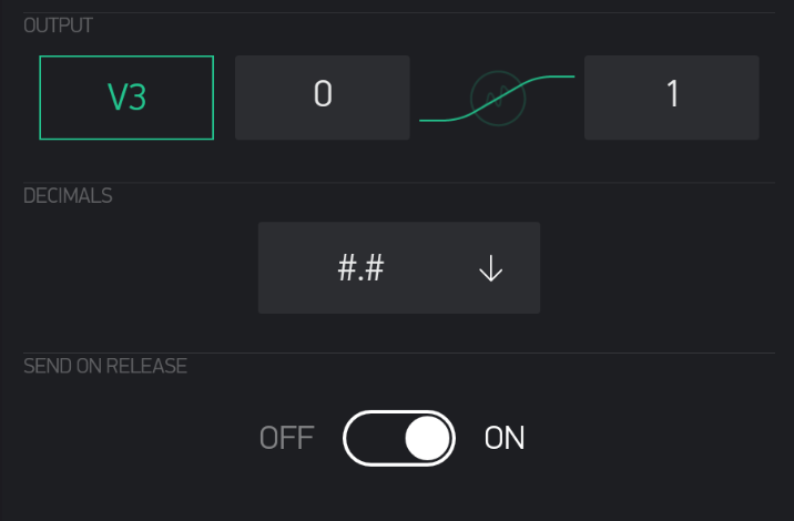
You can “slide” it ON and even returns back to OFF if you change your mind and don’t slide all the way or don’t release before sliding back… it only processes if released in the FULL ON position, then it automatically returns to OFF.
As per this example where either a button press or full slide & release will increment the interval…
The last sync command is only required if you actually need your code to actively register the return to OFF.
BLYNK_WRITE(V0) {  // Slider as "secure" Button - Set 0/1 Decimals to #.# and Send on Release ON
  if (param.asInt()) {  // If HIGH
    // Do ON stuff here, or call a function to do it
    Blynk.virtualWrite(V0, 0);  // Resets Slider LOW
    Blynk.syncVirtual(V0);  // Processes Button "release"
  } else {
    Blynk.virtualWrite(V0, 0);  // Resets Slider LOW
  }
}
Add in a non-blocking ‘delay’ timer (before turning OFF) if needed…
BLYNK_WRITE(V0) {  // Slider as "secure" Button - Set 0/1 Decimals to #.# and Send on Release ON
  if (param.asInt()) {  // If HIGH
    // Do ON stuff here, or call a function to do it
    timer.setTimeout(1000L, []() {  // non-blocking delay timer
      Blynk.virtualWrite(V0, 0);  // Resets Slider LOW
      Blynk.syncVirtual(V0);  // Processes Button "release"
    });  // END delay timer
  } else {
    Blynk.virtualWrite(V0, 0);  // Resets Slider LOW
  }
}
3 Likes
#28 - Dual LED Fade/Flasher for both Virtual and Physical LEDs
Here is a simpler? or just more compact Dual LED Fade/Flash that works with both Virtual and physical LEDs. It uses two nested Lambda type Timer Functions with if() logic to determine which timer is running… all in one Arduino function (speed switching aside)
UPDATE EDIT - I made some tweaks and added some 1ms delays in critical spots… it seems to work much nicer now and switch speeds smoothly… at least in my tests.

#define BLYNK_PRINT Serial // This prints to Serial Monitor
#include <ESP8266WiFi.h>  // for ESP8266
#include <BlynkSimpleEsp8266.h>  // for ESP8266

char auth[] = "xxxxxxxxxx";
char ssid[] = "xxxxxxxxxx";
char pass[] = "xxxxxxxxxx";
//char server[] = "xxx.xxx.xxx.xxx";  // IP for Local Server
char server[] = "blynk-cloud.com";  // IP for Cloud Server
int port = 8080;

const int blueLEDphysical = 12;  // GPIO ID - AKA D6
const int redLEDphysical = 14;  // GPIO ID - AKA D5
int redLEDvalue;
int blueLEDvalue;
int redblueLEDtimer;
int stepLED = 32;

BlynkTimer timer;


void setup() {
  Serial.begin(115200);  // BLYNK_PRINT data
  pinMode(redLEDphysical, OUTPUT);
  pinMode(blueLEDphysical, OUTPUT);

  WiFi.begin(ssid, pass);  // Connect to WiFi
  Blynk.config(auth, server, port);  // Configure Server settings
  Blynk.connect();  // Initialise Connection to Server

  // "Sacrificial" Timer - Seems to be needed when deleting timers as that will kill first timer created...
  redblueLEDtimer = timer.setTimeout(10L, []() {
    // Do nothing
  });  // END sacrificial Function

}

BLYNK_CONNECTED() {
  Blynk.virtualWrite(V2, 1);  // Set the pulse interval as OFF
  Blynk.syncVirtual(V2);
}


void loop() {
  Blynk.run();
  timer.run();
}

BLYNK_WRITE(V2) {
  switch (param.asInt()) {
    case 1:  // OFF
      timer.deleteTimer(redblueLEDtimer);  // Delete timer to have clean start
      Blynk.virtualWrite(V0, 0);  // Virtual LED OFF
      analogWrite(redLEDphysical, 0);  // redLEDphysical OFF
      Blynk.virtualWrite(V1, 0);  // Virtual LED OFF
      analogWrite(blueLEDphysical, 0);  // blueLEDphysical OFF
      break;
    case 2:  // Slow
      timer.deleteTimer(redblueLEDtimer);  // Delete timer to have clean start
      stepLED = 32;  // 8 levels of intensity per fade
      flashRedBlueLED();
      break;
    case 3:  // Medium
      timer.deleteTimer(redblueLEDtimer);  // Delete timer to have clean start
      stepLED = 64;  // 4 levels of intensity per fade
      flashRedBlueLED();
      break;
    case 4:  // Fast
      timer.deleteTimer(redblueLEDtimer);  // Delete timer to have clean start
      stepLED = 128;  // 2 levels of intensity per fade
      flashRedBlueLED();
      break;
  }
}


void flashRedBlueLED() { // Timer controlled alternating fade/flasher routine
  redLEDvalue = 0;  // 1st cycle starting level
  blueLEDvalue = 255;  // 1st cycle starting level
  redblueLEDtimer = timer.setTimer(stepLED / 2, []() {  // 1st cycle Lambda timer function
    Blynk.virtualWrite(V0, redLEDvalue);  // Output to Widget LED
    analogWrite(redLEDphysical, redLEDvalue);  // Output to Physical LED
    delay(1);  // Give a little time for things to settle
    redLEDvalue += stepLED;  // Increment red step
    Blynk.virtualWrite(V1, blueLEDvalue);  // Send value to Widget
    analogWrite(blueLEDphysical, blueLEDvalue);  // Output to Physical LED
    delay(1);  // Give a little time for things to settle
    blueLEDvalue -= stepLED;  // Decrement blue step
    if (blueLEDvalue == -1) {  // End of 1st cycle logic detector
      redLEDvalue = 255;  // 2nd cycle starting level
      blueLEDvalue = 0;  // 2nd cycle starting level
      timer.deleteTimer(redblueLEDtimer);  // Delete timer to have clean start
      redblueLEDtimer = timer.setTimer(stepLED / 2, []() {  // 1st cycle Lambda timer function
        Blynk.virtualWrite(V0, redLEDvalue);  // Output to Widget LED
        analogWrite(redLEDphysical, redLEDvalue);  // Output to Physical LED
        delay(1);  // Give a little time for things to settle
        redLEDvalue -= stepLED;  // Decrement red step
        Blynk.virtualWrite(V1, blueLEDvalue);  // Output to Widget LED
        analogWrite(blueLEDphysical, blueLEDvalue);  // Output to Physical LED
        delay(1);  // Give a little time for things to settle
        blueLEDvalue += stepLED;  // Increment red step
        if (blueLEDvalue == 256) {  // End of 2nd cycle logic detector
          flashRedBlueLED();  // Repeat main function again
        } // END 1st cycle logic
      }, 256 / stepLED); // END 1st Timer Function - calculation determines timer loop count
    } // END 2nd cycle logic
  }, 256 / stepLED); // END 2nd Timer Function - calculation determines timer loop count
}
8 Likes
#29 - (Triple  ) Synced Virtual and Physical Buttons using ESP32 hardware Interrupts
It has been awhile since I added to this topic… but here is my take on a common (at time of this posting) issue… synchronising Virtual and Physical buttons.
I chose to make this example work with or without Server connection, and the Physical GPIO states take priority on the reconnection (EG The App is set based on the hardware).
I also used three separate Virtual/Physical switch sets, just because , but the principle will work with 1 or many sets
As for “debouncing” the physical switches, aside from the interrupt using the falling signal there is also a 300ms timed flag setting to keep rapid toggling from occurring.
I used an ESP32 as that is what I had available… but I see no reason this couldn’t work on any device that supports hardware interrupts.
Oh, and I also tossed in OTA just to make sure there where no conflicts with the interrupts.
And finally… yes, the void loop() looks crowded (usually a big NO NO with Blynk)… but they be simple logic triggers and even the actual work functions that can be called are quick, so no problemo
Hope you enjoy and can make use of this example code.
For the App, you need:
- 1 Display Widget on V0 for the UpTime counter
- Three Button Widgets on V1, V2 & V3 (set as momentary, the code handles the “switch effect”)
On the ESP32 you need:
- Three Physical momentary buttons (no need for pullup resistors as that is handled in code) wired between GPIO and GND
- Three LED’s wired between GPIO and GND… you should probably use dropping resistors of course, although I never need to for testing.
And the code:
- Adjust GPIO pins and Cloud or Local Server as you desire (this is set for Local)
// Synchronise three Blynk Virtual momentary buttons and three physical momentary buttons, using ESP32 interrupts
// Physical buttons keep working even if device is disconnected from Blynk Server
// Upon reconnection, the state of physical buttons take priority and determine the state of App buttons

#define BLYNK_PRINT Serial // This prints to USB Serial Monitor
//#define BLYNK_DEBUG  // Optional, this enables more detailed Blynk diagnostics
#include <WiFi.h>              // for ESP32
#include <WiFiClient.h>        // for ESP32
#include <BlynkSimpleEsp32.h>  // for ESP32
#include <ESPmDNS.h>           // For OTA w/ ESP32
#include <WiFiUdp.h>           // For OTA
#include <ArduinoOTA.h>        // For OTA

// Setup timer - can have up to 16 iterations
BlynkTimer timer;

// Setup WiFi credentials
char auth[] = "xxxxxxxxxx";           // Device Auth
char ssid[] = "xxxxxxxxxx";           // WiFi AP
char pass[] = "xxxxxxxxxx";           // WiFi Password
char server[] = "xxx.xxx.xxx.xxx";    // Local Server IP
int port = 8080;                      // Local Server port

// Setup Physical GPIO connections
#define BUTTON_PIN_1 16
#define BUTTON_PIN_2 17
#define BUTTON_PIN_3 25
#define LED_PIN_1 22
#define LED_PIN_2 23
#define LED_PIN_3 26

// Setup variables
int btn_1_intrpt = 0;
int btn_2_intrpt = 0;
int btn_3_intrpt = 0;
int hold_1_flag = 0;
int hold_2_flag = 0;
int hold_3_flag = 0;
int conctFlag = 0;

void IRAM_ATTR ISR_1() {  // Interrupt 1 function
  btn_1_intrpt = 1;       // Set button 1 flag
}

void IRAM_ATTR ISR_2() {  // Interrupt 2 function
  btn_2_intrpt = 1;       // Set button 2 flag
}

void IRAM_ATTR ISR_3() {  // Interrupt 3 function
  btn_3_intrpt = 1;       // Set button 3 flag
}


void setup() {
  // Setup momentary buttons between GPIO and GND
  pinMode(BUTTON_PIN_1, INPUT_PULLUP);
  pinMode(BUTTON_PIN_2, INPUT_PULLUP);
  pinMode(BUTTON_PIN_3, INPUT_PULLUP);

  // Setup LED between GPIO and GND
  pinMode(LED_PIN_1, OUTPUT);
  pinMode(LED_PIN_2, OUTPUT);
  pinMode(LED_PIN_3, OUTPUT);

  attachInterrupt(BUTTON_PIN_1, ISR_1, FALLING);  // Setup Interrupt 1
  attachInterrupt(BUTTON_PIN_2, ISR_2, FALLING);  // Setup Interrupt 2
  attachInterrupt(BUTTON_PIN_3, ISR_3, FALLING);  // Setup Interrupt 3

  Serial.begin(115200);
  WiFi.begin(ssid, pass);            // Start Wireless connection
  Blynk.config(auth, server, port);  // Config Blynk parameters
  Blynk.connect();                   // Connect if available, continue code if not

  // Timed Lambda Function - UpTime counter
  timer.setInterval(1000L, []() {             // Run every second
    Blynk.virtualWrite(V0, millis() / 1000);  // Display the UpTime in Seconds
  });                                         // END Timer Function

  ArduinoOTA.setHostname("Blynk Button Sync ESP32");  // For OTA device identifying name
  ArduinoOTA.begin();                                 // For OTA

  Serial.println("ESP32 Device Active");
}


BLYNK_CONNECTED() {
  // Restore App buttons to match physical
  Blynk.virtualWrite(V1, digitalRead(LED_PIN_1));
  Blynk.virtualWrite(V2, digitalRead(LED_PIN_2));
  Blynk.virtualWrite(V3, digitalRead(LED_PIN_3));
}


void loop() {
  timer.run();                        // Keeps timers working
  if (Blynk.connected()) {            // Check for Server connection
    Blynk.run();                      // Keeps Blynk stuff working
  } else if (conctFlag == 0) {        // Continue if not already waiting for reconnection
    Serial.println("Blynk Offline");
    conctFlag = 1;                    // Block further connection attempt
    timer.setTimeout(600000L, []() {  // Allow reconnect attempt after 10 minutes
      Serial.println("Attempting Blynk Reconnection...");
      Blynk.connect();                // May take 30 seconds and will appear to block...
                                      // any physical button changes, but they do occur...
                                      // and they will register after connection timeout.
      if (Blynk.connected()) {        // If reconnected...
        Serial.println("Blynk Reconnected");
      } else {                        // If not reconnected...
        Serial.println("Reconnect Failed");
      }
      conctFlag = 0;                  // Release reconnection hold
    });                               // END Timeout Function
  }

  if (btn_1_intrpt == 1 && hold_1_flag == 0) {  // Only run if button and hold flag are correct
    btn_1_intrpt = 0;                           // Reset interrupt 1 flag
    hold_1_flag = 1;                            // Set hold 1 flag
    timer.setTimeout(300L, []() {               // Block further interrupt action for 300ms
      hold_1_flag = 0;                          // Reset hold 1 flag
    });                                         // END Timeout Function
    button_1_press_action();                    // Call button 1 function
  }
  btn_1_intrpt = 0;                             // Reset interrupt 1 flag

  if (btn_2_intrpt == 1 && hold_2_flag == 0) {  // Only run if button and hold flag are correct
    btn_2_intrpt = 0;                           // Reset interrupt 2 flag
    hold_2_flag = 1;                            // Set hold 2 flag
    timer.setTimeout(300L, []() {               // Block further interrupt action for 300ms
      hold_2_flag = 0;                          // Reset hold 2 flag
    });                                         // END Timeout Function
    button_2_press_action();                    // Call button 2 function
  }
  btn_2_intrpt = 0;                             // Reset interrupt 2 flag

  if (btn_3_intrpt == 1 && hold_3_flag == 0) {  // Only run if button and hold flag are correct
    btn_3_intrpt = 0;                           // Reset interrupt 3 flag
    hold_3_flag = 1;                            // Set hold 3 flag
    timer.setTimeout(300L, []() {               // Block further interrupt action for 300ms
      hold_3_flag = 0;                          // Reset hold 3 flag
    });                                         // END Timeout Function
    button_3_press_action();                    // Call button 3 function
  }
  btn_3_intrpt = 0;                             // Reset interrupt 3 flag

  ArduinoOTA.handle();  // For OTA
}


BLYNK_WRITE(V1) {
  if (param.asInt()) {        // If pressed
    button_1_press_action();  // Call button 1 function
  }
}


BLYNK_WRITE(V2) {
  if (param.asInt()) {        // If pressed
    button_2_press_action();  // Call button 2 function
  }
}


BLYNK_WRITE(V3) {
  if (param.asInt()) {        // If pressed
    button_3_press_action();  // Call button 2 function
  }
}


void button_1_press_action() {    // Via Interrupt 1
  if (digitalRead(LED_PIN_1) == 0) {  // If LED 1 OFF...
    Blynk.virtualWrite(V1, HIGH);     // Turn ON V1 Button
    digitalWrite(LED_PIN_1, HIGH);    // LED 1 ON
    Serial.println("BUTTON 1 ON");
  } else {                            // If LED 1 On...
    Blynk.virtualWrite(V1, LOW);      // Turn OFF V1 Button
    digitalWrite(LED_PIN_1, LOW);     // LED 1 OFF
    Serial.println("BUTTON 1 OFF");
  }
}


void button_2_press_action() {    // Via Interrupt 2
  if (digitalRead(LED_PIN_2) == 0) {  // If LED 2 OFF...
    Blynk.virtualWrite(V2, HIGH);     // Turn ON V2 Button
    digitalWrite(LED_PIN_2, HIGH);    // LED 2 ON
    Serial.println("BUTTON 2 ON");
  } else {                            // If LED 2 On...
    Blynk.virtualWrite(V2, LOW);      // Turn OFF V2 Button
    digitalWrite(LED_PIN_2, LOW);     // LED 2 OFF
    Serial.println("BUTTON 2 OFF");
  }
}


void button_3_press_action() {    // Via Interrupt 3
  if (digitalRead(LED_PIN_3) == 0) {  // If LED 3 OFF...
    Blynk.virtualWrite(V3, HIGH);     // Turn ON V3 Button
    digitalWrite(LED_PIN_3, HIGH);    // LED 3 ON
    Serial.println("BUTTON 3 ON");
  } else {                            // If LED 3 On...
    Blynk.virtualWrite(V3, LOW);      // Turn OFF V3 Button
    digitalWrite(LED_PIN_3, LOW);     // LED 3 OFF
    Serial.println("BUTTON 3 OFF");
  }
}
3 Likes