Problem PZEM-004T Version 3.0

Hi Ze_Pico,

When I click on Configure Module, below is what I see.

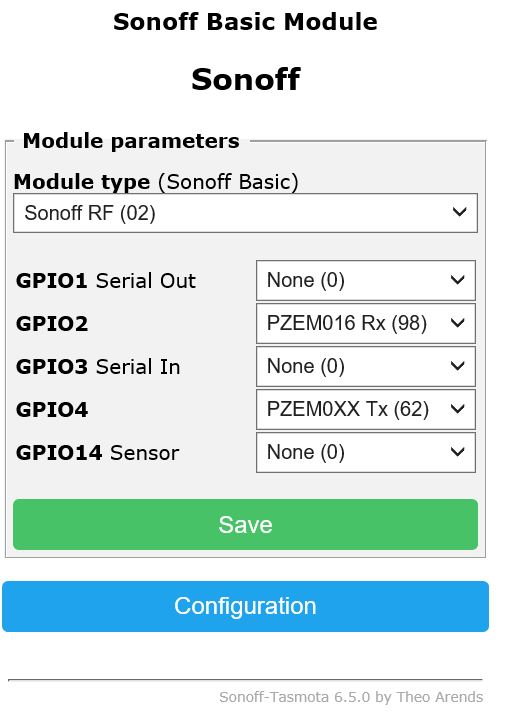
When I change the module type to Generic (18) then save it. Reboot the Wesmo by unplug/re-plug, the Module type get back to “SonoffRF” like the first image. (seem like it won’t save)

how did you flash your ESP Wemos D1 or NodeMCU ?
if this problem persist you should erase all flash .

Hi Ze_Pico,

What should be the correct wiring connection for Wesmo Mini to PZEM?

Thanks again for all your time on helping me on this.

Ze_Pico,

I use NodMCU-PyFlasher to flash the Wesmo. Yes, I did erase all the flash. Did re-flash the Wemo 7 times.

I will suggest to use arduino IDE to full erase the flash HERE

you must have Sonoff Generic (18) for PZEM to work like your post HERE

I will wait until you solve this problem then we can continue.

Hi Ze_Pico,

What you are saying is I have to download the “Sonoff-Tasmota-development” and use Aduino to upload?

Do I need to modify any file on that development package?

No, you just need to full erase your flash before uploading your bin file.
you don’t need Tasmota development .
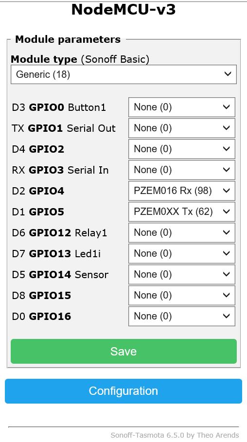
your bin file is OK as long as it shows PZEM in the configuration Menu.
you can full erase your ESP Flash with any sketch like in this picture.

Hi Ze_Pico,

Spent 6 hours today just try to figure out to flash 6 pcs of Wesmo Mini. Here is what I find out:

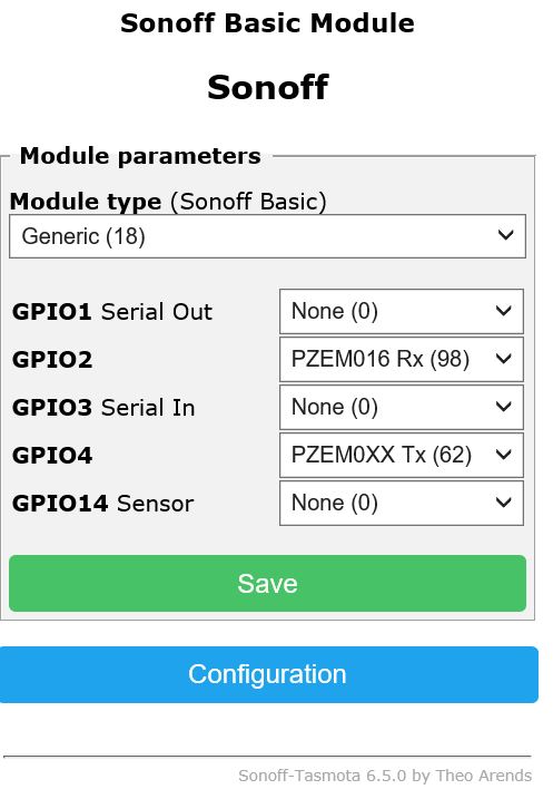
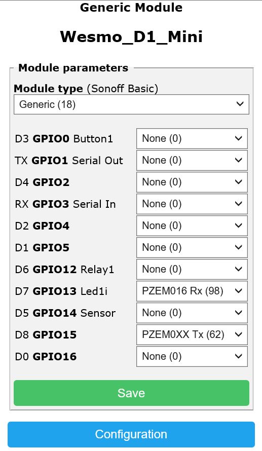
  • With Tastoma sonoff.bin ver 6.4 ==> yes, I can see the the Module Parameters like THIS.
  • With Tastoma sonoff.bin ver 6.5 ==> no matter how many time I flash, with different flash tools on 6 different Wesmo Mini, erase All Flash Contents ==> I can see on the Module Parameters is this:

And when connect the D7 to Rx and D8 to Tx ==> I lost the connection to Wesmo.

When I change from Wesmo to NodeMCU, the data display fine on the sonoff page with the following setup:

The questions I have now is:

  • Does Wesmos Mini works with Tamosa 6.5 for PZEM-004? if Yes, please help and let me know how to fix this.
  • Since I can get NodMCU to display the data, please let me know the next steps to integrate with Blynk so I can display the data on Blynk?

Regards,
Key

@key
glad that it works with you

I don’t have an answer for this but if PZEM can work on ESP-01 it should work on Wemos D1 mini.


unfortunately I don’t have Wemos D1 for testing now

1 Like

In this post you are showing that TASMOTA is working OK with Wemos D1
I think the problem is with your Flashing tools

Hi Ze_Pico,
That screenshot is from sonoff.bin v.6.4.
Yes, with v6.4, the Wesmo can display Module Type Generic 18 and I can save it. Since you request to install 6.5 therefore I flash it to 6.5 but the devices can’t save Module Type. :frowning:

I can re-flash the Wesmo back to 6.4 and test it again but please let me know what pin on Wesmos should I connect to PZEM? and what is the GPIO setup?

Regards,
Key

PZEM 004T v3 == MODBUS protocol

void GET_PZEM() {/*********************** PZEM004T mb ********************************/
PzemSerial2.begin(9600, SERIAL_8N1, RX2_PIN, TX2_PIN); node.begin(ID_pzem, PzemSerial2);
result = node.readInputRegisters(0x0000, 10);
if (result == node.ku8MBSuccess) { U_PR = (node.getResponseBuffer(0x00)/10.0f);
I_PR = (node.getResponseBuffer(0x01)/1000.000f);
P_PR = (node.getResponseBuffer(0x03)/10.000f);
PPR = (node.getResponseBuffer(0x05)/1000.0f);
PR_F = (node.getResponseBuffer(0x07)/10.0f);
PR_PF = (node.getResponseBuffer(0x08)/100.0f);
PR_alarm = (node.getResponseBuffer(0x09)); }
PR_den=PPR-PR_null; if (PR_odesli==0) {PR_odesli=PPR;} if ((PPR - PR_odesli)>=0.005) { odesli=1; if (sendsql<B000010) { sendsql=sendsql+B000010; } PR_odesli=PPR;}
}/===================================================================================/

/* *** PZEM modbus protocol ***

  • 0x0000 Volt 0.1V
  • 0x0001 I low 16 bits 0.001A
  • 0x0002 I hihg 16 bits
  • 0x0003 Power low 16 bits 0.1W
  • 0x0004 Power high 16 bits
  • 0x0005 Energy low 16 bits 1W
  • 0x0006 Energy high 16 bits
  • 0x0007 Freq 0.1Hz
  • 0x0008 Power Factor 0.01
  • 0x0009 Alarm status 0xFFFF/0x0000 alarm/not alarm
  • Holding register + Write
  • 0x0001 Power alarm 1W (2300W)
  • 0x0002 Modbus RTU address 0x0001-0x00F7
    */

TASMOTA sends data via the protocol to MQTT broker,for example Mosquitto (external or local). That-would their considered and to hand ONLY on Blynk ! You need another ESP. And specifically in your case better buy it PZEM-04 --v1-- the price $5. Otherwise, get ready to dance !

V1 has much worse design. I’d say- unsafe. I own 3 of them and decided not to use any. V3 looks better, as seen on pictures available.

Hi Marvin,

Are you able to make V3 to work with Wesmo? What pin do you connect it to?

Hi Lubomir,

How to implement the code that you provide, would you please provide with the steps instruction?

Regards,
Key

No, as I’m not using any of them (I ended up with RS-485 3-phase meter). But looking at V3 I can see much better high-side<—>low-side circuit isolation. The V1 has a design without any respect to the rules.
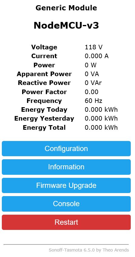
I didn’t followed the topic precisely, but It seemed for me, you had some readouts so the device is fine. Then it should work with any MCU connected to, YET IT MIGHT NEED some proper interfacing. But it would be a hard job to provide such a help on forum and still @Ze_Pico provided all (or almost all) info needed.

Hi Marvin7,

What device do you use for RS-485 3-phase meter, are they Smart? can you provide the link? do they have 2 phase device?

Hi Ze_Pico and everyone,

I was able to flash the Wesmo v6.5 with the following configuration:

As soon as I connect Wesmo D8 to PZEM Rx then I lost the connection to Wemso or can’t access Wesmo web interface.
What did I do wrong?
Did I make the right connection and setting?

#include <SoftwareSerial.h>  //  ( NODEMCU ESP8266 )
SoftwareSerial pzem(D5,D6);  // (RX,TX) connect to TX,RX of PZEM

#include <ModbusMaster.h>
ModbusMaster node;

double U_PR, I_PR,  P_PR,  PPR, PR_F, PR_PF, PR_alarm;
  uint8_t result;  uint16_t data[6];

void setup(){
  Serial.begin(115200); Serial.println("Start serial"); pzem.begin(9600); Serial.println("Start PZEM serial");
node.begin(1, pzem);  Serial.println("Start PZEM"); // 1 = ID MODBUS
}


void loop(){

result = node.readInputRegisters(0x0000, 10);
  if (result == node.ku8MBSuccess)  {
U_PR      = (node.getResponseBuffer(0x00)/10.0f);
I_PR      = (node.getResponseBuffer(0x01)/1000.000f);
P_PR      = (node.getResponseBuffer(0x03)/10.0f);
PPR       = (node.getResponseBuffer(0x05)/1000.0f);
PR_F      = (node.getResponseBuffer(0x07)/10.0f);
PR_PF     = (node.getResponseBuffer(0x08)/100.0f);
PR_alarm  = (node.getResponseBuffer(0x09));  
 } 

    Serial.print("U_PR:     "); Serial.println(U_PR);   // V
    Serial.print("I_PR:     "); Serial.println(I_PR,3);   //  A
    Serial.print("P_PR:     "); Serial.println(P_PR);   //  W 
    Serial.print("PPR:      "); Serial.println(PPR,3);   // kWh
    Serial.print("PR_F:     "); Serial.println(PR_F);    // Hz
    Serial.print("PR_PF:    "); Serial.println(PR_PF);  
    Serial.print("PR_alarm: "); Serial.println(PR_alarm,0);
Serial.println("====================================================");

  delay(1000);
}
1 Like