Ok I’ll try and let you know what happens, thanks Mille for technical support.
Ok I’ll try and let you know what happens, thanks Mille for technical support 


Hello !
According to the specifications given for v.3.0 of PZEM-004T it measures/reports also the frequency and the power factor. I’m not sure if the library https://github.com/olehs/PZEM004T is able to read these new electricity parameters.
Did you run any test how to read those parameters apart voltage,current, power and energy ?
Thanks !
Или может это поможет
Hi Ze_Pico,
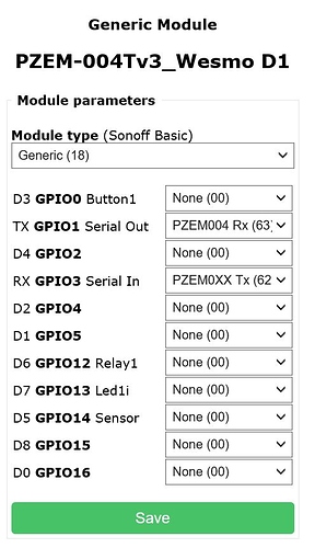
I just flashed the Wesmo mini with Tasmota and configured as shown below.
- Tx on Wesmo connected to Rx on PZEM
- Rx on Wesmo connected to Tx on PZEM
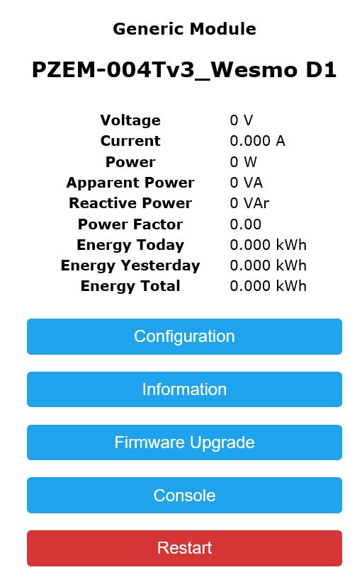
==> The reading still show nothing. (Yes, I do have 110V AC to PZEM)
When connect:
- D8 on Wesmo connected to Rx on PZEM
- D7 on Wesmo connected to Tx on PZEM
==> Wesmo has no response, I can’t get into the Wesmo web interface.
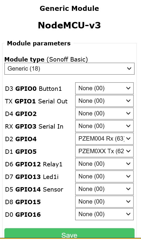
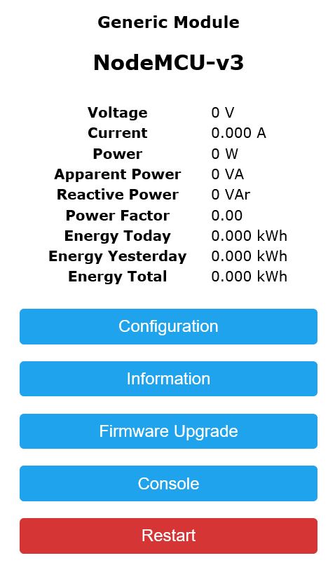
I also tried to replace the Wesmo with NodMCU v3 and flashed it with Tasmota but the reading still show zero.
Here is the setup for NodeMCU v3:
- G on NodMCU connected to G on PZEM
- VV on NodMCU connected to 5V on PZEM
- D1 on NodMCU connected to Rx on PZEM
- D2 on NodMCU connected to Tx on PZEM
Would you please let me know what did I do wrong and how to fix it so the reading on show up on the Tasmota?
-
- Before compiling check your
"my_user_config.h"
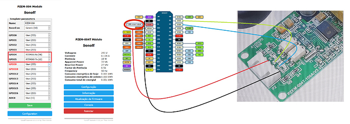
to see if PZEM section is not commented as in the picture below
- Before compiling check your
-
- for PZEM_AC v3 set Tasmota to “PZEM016 Rx (98)”
Hi Ze_Pico,
Since I’m new to Tasmota, I think I missed some steps here. All I did is just flash the Wesmo/NodMCU with Tasmota firmware, I haven’t do and sketch upload or modify the config.h file yet.
Could you please let me know where can I download those for PZEM-004T v3 sketch like the one on your posted?
What is the the correct pin connection between Wesmos/NodMCU and PZEM-004T v3?
Regards,
Key
I know @PeteKnight suggested it already to you, so…Why don’t you try with simple USB<–>serial (TTL) bridge, like FT232 (or many other) connected to PC,using official PZEM software (or ANY terminal) and verify if your unit is OK or not…
@key
OK, we will do it step by step.
can you show me your configuration page especially the last line to know the version you are using.
like Here
Ok ok
I will carry out the steps you described with the FW Tasmota in order to try if everything works. You have been very kind, as soon as all this is done you will update on the process and the operation. Thank you very much for the help you are giving us.
Hi Ze_Pico,
Here is the steps that I did on Wesmo D1 Mini and PZEM-004 v3 (Just to make sure, I get another set of brand new Wesmo and PZEM)
1- Flash Wesmo with Tasmota v6.5 sonoff.bin (download from HERE)
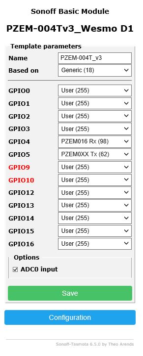
2- Access Wesmo Sonoff page and configure it like this:
Note: On the new Sonoff 6.5, I don’t see any page on Sonoff that display voltage.
3- Connect Wesmo 5V to PZEM 5V
4- Connect Wesmo G to PZEM GND
5- Connect Wesmo D7 to PZEM Tx
6- Connect Wesmo D8 to PZEM Rx
As soon as I connect all the wires like above, I get no response to the Wemos
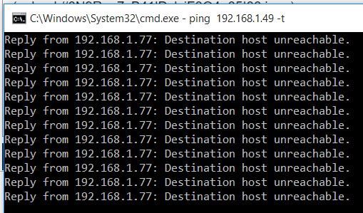
Remove D7 & D8 then I get the response
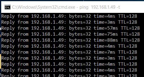
Please let me know what is the next steps that I need to do?
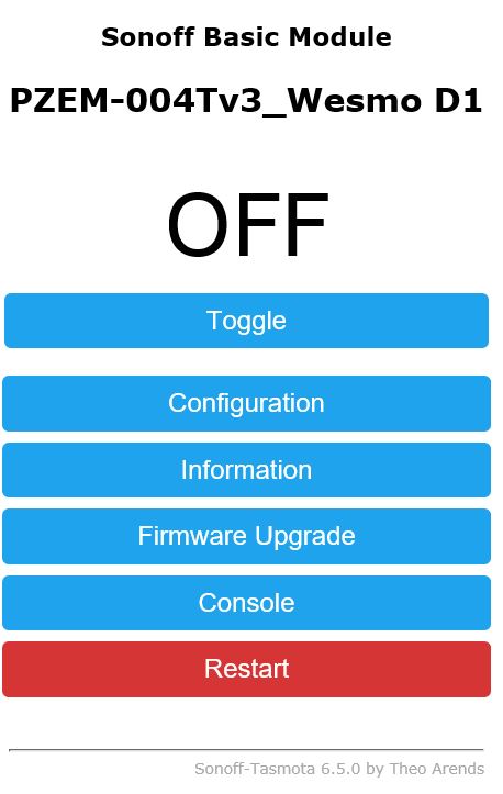
first your Tasmota version is 6.5.0 and that is OK.
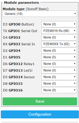
Next step why you are using Configure Template you should use Configure Module.
can you adjust your configure module to this picture.
and tell me what you see in Main Menu
don’t forget to save your configuration.
GPIO 4 и GPIO 5 это D1 и D2 !!! Причем тут D7 и D8 ??? Либо провода перекинь или GPIO 13-15 выставь
@svs2007m
not every body can translate Russian to English or have a translator within his browser.
if you can do it for us it will facilitate our discussion.
thanks.
It has the wrong setting ! The wires are connected to D7 and D8. And Tasmota is set to D1 and D2
that’s correct and I am trying to do it step by step for this reason.


