My home automation projects built with MQTT and Node Red

I thought I’d start a topic about some of the home automation things I’m doing with Blynk.

We live in London, England, and also have a holiday home in Spain where we spend around 4 months of the year. Most of my home automation projects are based in the Spanish home and are aimed at simplifying day-to-day life while we’re there. My wife is disabled, and finds new technology a bit of a challenge, so all the projects that I’ve created are aimed at being practical, easy to use and reliable.

Lets start with a bit of an introduction to the technology platform that I’m using…

Part 1 – Background

I don’t use Blynk in the same way as most other people, so this post is aimed at explaining the technology used and hopefully demonstrating that it’s worthwhile going down this route if you’re building complex projects.

The core of my system is a Raspberry Pi 3 running Node-Red and the Mosquitto MQTT server. I use the Blynk cloud server for simplicity and reliability.

Node-Red is a graphical programming/workflow environment that is extremely powerful and it can be expanded by writing your own functions in a language which is very similar to Arduino C+. It’s also very simple to import additional ‘Nodes’ that are contributed via the Node-Red community and which add additional functionality. One of the ones I use is set of nodes developed and maintained by @gab.lau that give integration with Blynk. This is called node-red-contrib-blynk-ws. Other nodes I use on a regular basis allow integration with Amazon Alexa (node-red-contrib-alexa-home-skill) and Ikea Tradfri/Philips Hue lighting. There’s also a very powerful and flexible timing node developed by @scargill called node-red-contrib-bigtimer which I use to handle all of my scheduling.

MQTT is a message transfer protocol that allows devices to transfer commands and data very easily. One way to visualise how MQTT works is to think of it as a standard folder/directory system that you might find on a Windows PC where you can drop messages for various programs to pick-up and use. Say you set-up a folder structure called:

../Home/Lounge/Lights/Light_1/Command/

You can then drop commands like “On” / “Off” (or “1” / “0”) in to this folder so that the devices that monitor this folder see the command, pick it up and do something with it.
In MQTT terms, putting a message in a folder is called Publishing and monitoring a folder is called Subscribing. The folders themselves are called Topics.

Obviously you don’t use a Windows file structure to achieve this, everything is handled in the background by the Mosquitto MQTT server when it comes to where and how the messages are stored. But, thinking of it in the same terms as you would when setting-up a folder structure to store data on your PC can help you to create a logical topic structure.

A Simple Example
Let’s take a look at a simple example of how you could use Blynk, Node-Red and MQTT together to control a light…

A simple system could have:

  • A mobile phone or tablet running Blynk, with a project that has a single on/off button widget connected to virtual pin 1.

  • A simple Node-Red flow that takes the output from the V1 button and writes it to our MQTT topic of Home/Lounge/Lights/Light_1/Command

  • An MCU device (in this case a Sonoff switch that will control a light), running software that connects to the local Wi-Fi and subscribes to the Home/Lounge/Lights/Light_1/Command topic. If the Sonoff receives a “1” then it will activate the relay to turn the light on, if it receives a “0” it will deactivate the relay to turn the light off.

The Node-Red flow for this would simply be:

The green node on the left is the incoming data from the Blynk button widget (a “0” or “1”), the pink node on the right outputs the same message (“0” or “1”) to the MQTT Topic.

You might ask “Why go to all this bother – why not just use a simple Blynk sketch”. The answer us that for something as basic as this then yes, a simple Blynk sketch is easier and quicker. However, it’s very easy to add-in other devices and get them talking to each other, something that isn’t as simple to do using just Blynk.

One of the things I use this system for is controlling my air conditioning, cooling fans and wall heaters. I have multiple temperature/humidity sensors, a Nextion touch screen, Infra-Red transmitters (to control the aircon and fans), Sonoff switches (to control the heaters) and a 433MHz receiver linked to door & window sensors (to warn if they are open when using the heating or air conditioning). This gives 8 devices that all talk to each other and interact in some way.
Doing this with Blynk alone would be a challenging task, so I use Blynk for what it’s great at – giving app control over settings, regardless of where you are in the world at the time.

Adding-in Alexa Voice Control
Building on my previous example, here’s how you would add-in Amazon Alexa voice control for the light that we’ve just set-up.

The Alexa “plug-in” for Node-Red allows you to name your devices however you wish. In this case I’ve gone with “Light 1” again. This is the Grey node bottom left. The output from the Alexa node takes the form of “TurnOnRequest” or “TurnOffRequest” and these strings need to be translated into “1” and “0” so we use a Change node (the yellow one at the bottom for this) for this.
As we also want the Blynk switch widget to stay synchronised, we need to write the output of the Change node back to pin V1, as well as to the MQTT node, so we use a Blynk output node (green, bottom right).

Once you’ve asked Alexa to discover your new device, saying “Alexa, Turn Light 1 On” will activate the Sonoff and turn the light on, as well as updating the app to show the switch widget on V1 as being On. I doubt that there’s an easier or quicker way to add Alexa integration to any project.

[Update December 2021] I’ve now moved away from the Alexa plug-in used in the screenshots and started using the node-red-contrib-virtual-smart-home plug-in instead.
The original plug-in had started to give “I’m not sure what went wrong” responses (despite the device responding correctly) when values were specified in the command (such as “Alexa, set the fan to 3”). The new plug-in is much simpler to use, and devices are added and deleted when the Node-Red flow is deployed without the need to ask Alexa to discover new devices. It’s also much more responsive than the other plug-in and eliminates the error responses that I had started to get.
It also allows a wider variety of Alexa device types to be specified when adding a new device.

Graphical Programming versus Coding
As an example of how easy it is to achieve results using the graphical programming environment of Node-Red, this is how the Change node is configured to translate the output from the Alexa node into the format we want:

It’s extremely simple to do things like this and I’m sure some would find it easier than writing the corresponding “if” statement in code.
Having said that, it you want to do this in a user defined function then there’s a node to allow you to do that. Personally, I tend to write functions that can perform multiple tasks to reduce the node count, but it depends on the complexity of the flow and what I’m trying to achieve.

Hopefully this has helped to explain a bit about what Node-Red and MQTT are, and how this combination can be used with Blynk.
If you’re interested in creating your own Node-Red and MQTT setup on a Pi then I’d recommend taking a look at the installation script that @scargill has created on his tech blog website:

In the next posts I’ll start to get into more detail about the real world projects that I’m working on, starting with my door-entry system that I’ve created in Spain.

Pete.

27 Likes

Part 2 – Door Entry System

If you’ve not read Part 1 yet then I’d suggest that you do, before going any further.

Our home in Spain has gate to the street which has a conventional speech-only door entry system that allows us to talk to people at the gate and release the lock if we wish. The gate also has a lock that can be opened using a conventional key, but getting the key in the lock and opening the gate can be a bit fiddly, especially in the dark after a few beers!

Our community swimming pool has a door entry system controlled by RFID key fobs, where each house on the urbanisation has a fob with a different code. I decided that adding a similar RFID system to the gate of our house would be a nice improvement, and having just one key fob that opened both the pool and the house gate would be the most sensible approach.

After a few false starts, I eventually managed to work out that the key fob for the community pool is a Mifare 1k system. I bought a Wiegand protocol waterproof reader that can read the Mifare fobs and initially built a stand-alone reader using an Arduino Mini. This worked okay, but I realised that I really wanted more functionality, such as the ability to release the gate remotely (more about the thinking behind that later) and to know when the gate had been opened (handy to monitor when our keyholder does his property checks when we’re not there).

Copying the pool entry fob proved trickier than I thought, as a random code is embedded into most fobs when they are made, but I needed more fobs with the same User ID code as our original one. I eventually managed to source fobs with a re-writeable block zero (which is where the User ID is stored) at a sensible price so I ordered some and a writer to be able to clone my existing fob.

I recently replaced the Arduino Mini with a Wemos D1 Mini Pro (chosen because I needed an external antenna) and “Blynkified” the gate.

This worked well gave the ability to release the gate via the app and to keep a log (using a Table widget) of when the gate has been released and what method has been used to release it (Blynk app, RFID fob or 433MHz button – more on that later). It also logs the User ID code from any unidentified RFID fobs so I can see if someone has tried their fob against my reader.

Having done this, the door entry for the gate still didn’t really give all the functionality we wanted it to. The gate is at the front of the property and the door entry intercom is in a room at the rear of the property. We have a window at the front that overlooks the gate, and in practice we find that it’s easier to go to the window and look out, and often open the window and speak to the person at the gate. This works better because you can see who you’re talking to, and also because if the visitor is Spanish then the language barrier seems less problematic when you’re speaking face to face rather than over the intercom. The disadvantage to this approach is that if you then decide that you want to let the person in, you either have to walk to the intercom handset and release the gate (then usually go back to check that they entered okay) or rummage around and find your phone, open the Blynk app and then release the gate.

Obviously a video Entryphone would solve some of these issues, but installation could prove problematic and I wanted a cheaper and simpler solution. I eventually settled on a 433MHz battery powered button located near the window, and a 433MHz receiver attached to a Wemos D1 Mini to act as 433 to MQTT gateway. This allows the button to be pressed to release the gate whilst standing at the window and it’s much quicker and easier than either of the other two options.

The button transmits a preset code on the 433MHz frequency, and when the MQTT gateway receives that specific code it sends an MQTT instruction via the server to the gate to release the lock.

The final enhancement (for the time being at least) was to change the system so that it turns on the security lights at the front of the house for 2 minutes when the gate is released, provided it’s dark outside. This uses a Sonoff switch wired into the PIR lighting and the Node-Red “Big Timer” node from @scargill to calculate if it’s dark or not. The outside lighting is actually divided into four zones, each of which is controlled by a separate Sonoff and I’ll talk a bit more about that in a later installment.

So, this is a diagram showing how various devices talk to each other…

And this is what the Node-Red flow looks like:

The flow actually has a couple of features I’ve not yet mentioned: RSSI data from the Wemos Pro on the gate, via an MQTT message that’s sent every 5 seconds and pushed out to the app; an online/offline LED in the app to tell me if the Wemos Pro is connected to the network and; feedback to the “Open Gate” button widget in the Blynk app so that it turns on momentarily when the gate is released via either the RFID tag or the 433MHz button.

Being able to release the gate via the RFID tag is my most important priority, so my code running on the Wemos Pro that’s connected to the RFID reader is written so that it continues to work in stand-alone mode if the Wemos can’t connect to either the Wi-Fi or the MQTT server. It tries briefly to re-connect every 60 seconds if it’s in stand-alone mode, so it goes back to IoT mode when the Wi-Fi etc. is back up and running - without affecting the operation of the RFID system.

I’m currently kicking around a few more enhancements:

  • I’d like to install a microswitch to tell me when the gate is closed. That’s easy from a software point of view, but not so easy from a practicality and reliability angle. I’d probably set-up a Blynk alert if the gate is left open for a certain duration.

  • I also plan to install a CCTV camera that will show me an area that includes the gate, and I might be able to integrate this into the Blynk app, and possibly add a tablet near the door entry intercom to display the CCTV image like a video Entryphone. The CCTV will primarily be to allow me to monitor activity while I’m away, but it could make the door entry system more flexible as well.

  • A system that will send a Blynk alert to tell me when the call button on the door entry system has been pressed. This should be easy to achieve with a simple opto-isolator from the door entry call button. Having this facility will be useful when we have visitors but we’re out of earshot of the door entry system.

Thanks for taking the time to read this, but please don’t ask me for code or for the Node-Red flows.
My setup is very specific to what I’m doing and if you already have the skills then you’d be better starting from scratch to create your own system that meets your specific needs. If you don’t have the skills then I don’t really want to spend my time trying to explain the details and guide you through editing the code and flows to suit your own requirements.

This series of posts are intended to show people what can be achieved quite easily with a Node-Red/MQTT/Blynk setup and to maybe give people inspiration and a few ideas for their own projects.

In future posts I’ll try to explain my outside lighting, heating controller, indoor lights, power cut monitor, blinds controller and weather station projects.

Pete.

12 Likes

83 posts were split to a new topic: Comments about automation projects built with MQTT and Node Red

Part 3 – Outside Lighting

This doesn’t sound like a very interesting home automation subject, but actually it makes a big difference to the way that we enjoy the outside space at our home in Spain, especially when we socialise outside in the warm summer evenings and nights.

I’ve installed some external LED floodlights that are linked to PIR detectors and divided into zones. Each zone covers a different outside area and has two or three PIR detectors so that no matter which direction you enter the zone from it turns the lights on for a period of time.

I wanted to add a method of overriding the PIR detectors, which would put the lights on for a longer period – handy when you’re sitting outside eating and drinking, but not moving about enough to keep the PIR detectors constantly triggered; also handy when you’re parking the car, as the movement of the car doesn’t normally trigger the PIRs.

I started by adding a Sonoff Basic to each of the zones and using Blynk as a way of triggering a countdown timer to put the lights on for a pre-set time – 60 minutes in the eating area and 5 minutes in the area where the car is parked.
This worked well, but meant that everyone who wanted to control the lights would need the Blynk app installed on their phone and access to the shared project. Not very convenient for guests, and this approach would mean that our guests would still be able to control the lights long after they’d returned home. I think the fact that it’s not possible to revoke access for specific users is one of the main drawbacks of the Blynk [Legacy] shared app.

As I’d already created a 433MHz to MQTT gateway for my door entry system (see Part 2), I decided to use this as an additional way of starting the countdown timers.
I also added-in Amazon Alexa voice support (I explained this briefly in Part 1), so that it’s very easy to turn on all of the outside lights for a few minutes simply by saying “Alexa, turn the Outside Lights on”, when you’re within earshot of an Alexa device. This is handy when we’re sat indoors at night and hear a strange noise outside and want to quickly put the lights on to see what has caused it. So far all we’ve seen are the local cats disappearing into the shadows, but it’s good to have a quick and simple to use way of scarring-off potential prowlers.

These are the 433MHz fobs that I give to guests:

The red button (A) activates the lights in the seating area for 60 minutes. The other button (B) cancels the timer.
I also have a 4 button fob on my keyring. Buttons A and B work the same as the other fob, Button C puts the lights on in the parking area for 5 minutes and Button D puts all the lights on for 2 minutes. Button B cancels all of these operations.
You’ll see me demonstrating buttons A and B on this fob this in the video at the end.

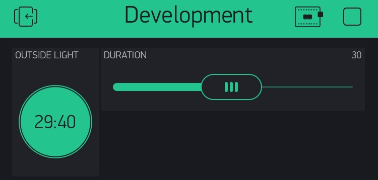
To explain in more detail what the coding behind this this looks like I created an example in Node-Red that controls just one lighting zone, to demonstrate the countdown timer process and show how the various trigger devices link together. I also decided to use a Slider widget in the example to allow the user to control how long the light should stay on for, once triggered.

Let’s start by looking at the trigger processes (don’t worry about the spider’s web of connections at this stage, I’ll come to those later):

Flow 1

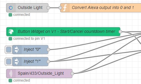
This part of flow shows inputs from

  • The Alexa output from an Alexa device I’ve named “Outside Lights”
  • A Blynk button widget on V1
  • Two “Inject” nodes that allow off/on (0/1) commands to be issued directly from the Node-Red flow
  • The MQTT commands that come from the 433MHz to MQTT gateway (or any MQTT software that can publish to a topic)

The part of the flow that gets the value from the Slider widget on V2 looks like this:

The value from the slider widget (in minutes) arrives into the green node. The orange Function node simply multiplies the number of minutes set using the slider by 60 to turn it into seconds, then stores the value in a global variable called Countdown_Timer.

The code for that looks like looks like this:

global.set('Countdown_Timer',(msg.payload*60)); // Take the minutes value from te slider widget and convert to seconds

Now we’ll see how these triggers and the slider link together:

The wiring looks twice as complex as it could, because of the decision to use a slider to set the countdown time period.
This slider is attached to V2, and whenever an On command is received from any of the trigger devices we need to do the equivalent of a Blynk.syncVirtual(V2); command in C++. This is done with the green Sync node that I’ve called “Sync value from V2 slider”. This simply goes and fetches the slider value from the Blynk cloud server and triggers the equivalent of a BLYNK_WRITE(V2);, so that the current value of the slider setting is pushed to the green “Slider Widget on V2 - Countdown minutes” node.

The trigger device nodes are also connected to a function “Start/Cancel Countdown Timer” Once one of the trigger devices has sent a command to this function it simply simply updates a few global variables, depending on whether it received a 1 or a 0. The code looks like this:

if (msg.payload ==="1")                         // Do this if we received an On command "1"
{
    global.set('Light_On_Flag',true);           // We annt the light to be on 
    global.set('MQTT_Msg_Sent_Flag',false);     // But the MQTT message to turn the light on hasnt been sent yet
}

else                                            // Do this if we received an Off command "0"
{
    global.set('Countdown_Timer',0);            // Reset the countdown timer to zero
}

return msg;                                     // Output the "1" or "0" as the message payload   

The command is also passed out the other side of the function to update the button widget on V1. This is so that the button in the app stays synchronised with all the other trigger devices. If Alexa turns the lights on then we also want the Blynk button widget to reflect this.

Because the Alexa node can be used to both turn the light on/off and to set the duration in minutes that you want the light to stay on for, it has two outputs. The code within the function directs the appropriate command to the correct output, and does a bit of sense-checking on the duration. It would be perfectly acceptable to Alexa to say “Alexa, set Outside light to minus 100”, or “… to 50,000”. In this example, I’ve set the slider widget so that it’s range is 1 to 60, so my code ensures that these are the minimum and maximum values that are outputted from the function node.
Of course, if I say “Alexa, set outside light to 50,000” Alexa will respond “Outside is set to 50,000” but the slider value and the duration of the countdown will be capped at 60 minutes.

Here’s the code for that:

var OnOff;
var Duration;

if (msg.command==='TurnOnRequest')
{
    OnOff="1";
    return [null, {'payload': OnOff}];
}

if (msg.command==='TurnOffRequest')
{
        OnOff="0";
        return [null, {'payload': OnOff}];
}

if (msg.command=="SetTargetTemperatureRequest")
{
    Duration=msg.payload;
    
    if (Duration <=0)
    {
        Temp = 1
    }
    if (Duration >60)
    {
        Duration = 60
    }
    return [{'payload': Temp}, null];
}

The real processing work is done in this part of the flow:

The blue/grey node on the left hand side called “Auto inject something once every second” does exactly what it says on the tin – it sends a pulse of data out once every second. It doesn’t matter what this data is, it’s simply needed to trigger the “Reduce remaining time by 1 sec” function. Think of it like a Blynk timer calling a function once every second.

The orange “Reduce remaining time by 1 sec” function has two outputs. One sends the remaining countdown time in MM:SS format to the Blynk button widget on V1. This is done using the green node which is a Blynk Set Property node. In this case the property that is being updated is the “On Label” property for the button, so that when the light is on, the button shows the remaining time:

The other output goes to the pink MQTT Output node. This is used to turn the Sonoff Basic that controls the lights on and off. The code running on the Sonoff subscribes to the MQTT topic called “Spain/Outside_Lighting/Seating_Area” and when it sees a “1” in this topic it activates the lights, when it sees a “0” in this topic it deactivates the lights.
I only want to send an MQTT message once at the start and once at the end of the countdown timer process, so the code in my function handles this.
This is the code in the “Reduce remaining time by 1 sec” function. You have to remember that it’s called once every second, regardless of whether the lights are on or off, and that each time it’s called the local variables are wiped clean.

// Initialise the local variables and update them with the GLOBAL variables
var Countdown_Timer = global.get('Countdown_Timer')             //Remaining time that the light stays on for
var Light_On_Flag = global.get('Light_On_Flag')                 // Flag to show if the light is/should be on
var MQTT_Msg_Sent_Flag = global.get('MQTT_Msg_Sent_Flag')       // Flag to show if we've sent the MQTT On message yet
var Completed_Flag = global.get('Completed_Flag')               // Flag to show if we've finished the countdown yet

// Initialise the local variables
var Minutes = 0 // Intermediate variable to hold remaining whole minutes as Integer
var Seconds = 0 // Intermediate variable to hold remaining seconds (0-59) as Integer
var Minutes_String = "" // Intermediate variable to hold remaining whole minutes as String
var Seconds_String = "" // Intermediate variable to hold remaining seconds (0-59) as String
var MM_SS_String = "" // Intermediate variable to hold remaining in MM:SS format String


if (Light_On_Flag && Countdown_Timer>=1)    // If the light is/should be on then we execute this loop until countdown reaches 1
{
    Countdown_Timer = Countdown_Timer-1;    // Decrement the countdown
    global.set('Countdown_Timer',Countdown_Timer);  // write the new countdown value back to the global variable to store it
    Completed_Flag = false;                         // We're not done yet
    global.set('Completed_Flag',false);             // write the completed flag back to the global variable to store it
    Secs_to_MM_SS();                                // Call the function to convert the remaining time in seconds to MM:SS format
    node.status({fill:"green",shape:"dot", text: MM_SS_String});    // Display the result on the node, to give feedback

   if (MQTT_Msg_Sent_Flag!==true)   // If we've not sent the MQTT message to turn the light on yet, do it now...
    {
        node.send ([{'payload': MM_SS_String}, {'payload': "1"}]); // Write the MM:SS to output 1 and the MQTT on instruction ("1") to output 2
        global.set('MQTT_Msg_Sent_Flag', true);     // Set the flag to show that we've now sent the MQTT instruction
    }
    else    // If we have sent the MQTT On instruction then we don't needs to send it again...
    {
        node.send ([{'payload': MM_SS_String}, null]); // Write the MM:SS to output 1 and nothing to output 2
    }
}
else    // We get here if the countdown timer is 0 - This will happen once every second when the light is off!! 
{
    if (Light_On_Flag && Completed_Flag!==true) // Ifr the MQTT message to turn the light off hasn't been sent yet, do this... 
    {
        node.send ([{'payload': "--:--"}, {'payload': "0"}]); // Write "--:--" to output 1 and an MQTT Off command ("0") to output 2 
        Completed_Flag = true   // we're now done
        global.set('Completed_Flag', Completed_Flag);   // write the completed flag back to the global variable to store it
        node.status({text: " "});       // Clear the display on the node
        Light_On_Flag = false   // The light is now off
        global.set('Light_On_Flag', Light_On_Flag); //Update the flag in the global variable
    }       
}


function Secs_to_MM_SS()    // function to convert the remaining time in seconds to MM:SS format
{
    Minutes=parseInt(Countdown_Timer/60);   // Get the number of whole minutes remaining - Use and integer to round correctly
    Seconds = Countdown_Timer-(Minutes*60); // Get the number of seconds remaining (0 to 59) for the MM:SS display 
    
    if (Minutes<10)
    {
        Minutes_String = "0" + Minutes.toString()   // If less than 10 minutes remaining then add a leading zero and convert to a string       
    }
    else
    {
        Minutes_String = Minutes.toString() // If more than 10 minutes remaining then no need to add a leading zero - just convert to a string             
    }

    if (Seconds<10)
    {
        Seconds_String = "0" + Seconds.toString()    // If less than 10 seconds remaining then add a leading zero and convert to a string           
    }
    else
    {
        Seconds_String = Seconds.toString()  // If more than 10 seconds remaining then no need to add a leading zero - just convert to a string                 
    }
    
    MM_SS_String = Minutes_String + ":" + Seconds_String // Create the MM:SS string from the minute and second strings
}

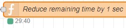
I’m not going to explain the code in detail here, as I think the in-code comments do that fairly well. The only thing that may not make any sense if you’ve never seen Node-Red before is this bit of code:
node.status({fill:"green",shape:"dot", text: MM_SS_String});
Each node has the ability to display text below the code, to provide information to the user. You’ll have noticed messages like “connected to pin V1”. These are very handy when troubleshooting, and the line of code above displays a green dot with the remaining countdown time in MM:SS format when the light is on.

Flow 5

Here’s the full flow:
You’ll obviously have been paying attention, so you’ll have spotted couple of things that I haven’t mentioned yet…

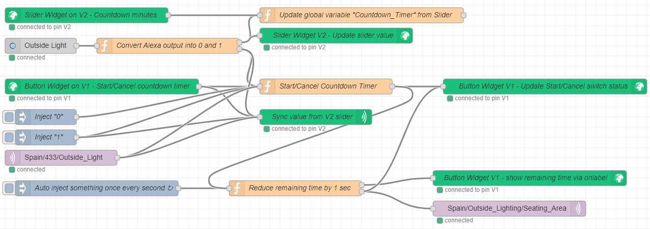
There’s a connection from the “Start/Cancel Countdown Timer” function to the “Reduce remaining time by 1 sec” function. This isn’t really necessary, but it ensures that when one of the input devices pushes a message into the “Start/Cancel Countdown Timer” function it immediately passes through to the “Reduce remaining time by 1 sec” function. This triggers the function immediately, rather than having to wait until the next 1 second trigger come from the auto inject node. This just makes the lights a bit more responsive, otherwise there could be a response time of up to 1 second before the lights go on or off.

There’s also a connection from the second output of the “Reduce remaining time by 1 sec” to the “Button Widget V1 - Update Start/Cancel switch status” node. This is important, as when the countdown timer reaches the end and sends it’s “0” message to the MQTT node to turn off the light, it also needs to turn the widget button off in the app, to keep everything synchronised.

I made a short video showing it in action. In the video I’ve mirrored the Blynk screen from my phone so that you can see more clearly what’s happening with the button and slider widgets. I’ve also demonstrated that you can use any MQTT client to publish a 1 or a 0 to the “Spain/433/Outside_Light” topic to turn the light on and off, in this case using a program called MQTTfx.

Turn up the sound if you want to hear the Alexa commands and responses.

As you can see, any combination of the input devices can be used to turn the timer on and off. What I’ve not shown is the timeout timer ticking down to zero and switching the light off automatically, but trust me that this works too.

The next instalment will be about my heating/air conditioning controller. This will be a very high-level overview as it’s quite a complex system, but it might provide a bit of food for thought for anyone wanting to embark on a similar project.

Pete.

12 Likes

Part 4 – Climate Control

In this installment, I’ll talk about my heating and cooling controller. It will be MUCH higher level that the last installment, as the system is quite complex and extremely specific to our situation. Hopefully it might inspire others to look at similar projects of their own.

This is still work in progress to a certain extent. The basic climate control functionality works well and I’ve developed and tested some additional features, but in some cases I’ve yet to implement them fully.

As we only spend around 4 months of the year in Spain, it’s actually quite difficult to make much progress with the project. I tend to develop bits and pieces when I’m at home in the UK, but finding time to implement them when we’re in Spain can be a bit tricky. Also, you cant really test the heating functionality in the middle of summer and vice versa.

Overview

The system controls the heating and cooling devices in our living room of our holiday home in Spain.

The climate in our part of Spain is hot in summer and surprisingly cold in winter. Spanish homes are designed to stay cool, so keeping them warm can be a major issue in winter.

Heating - this is provided by an inverter air-conditioning unit and three wall-mounted 400w heating panels. There is also a built-in gas fire, but this can only be used manually. I’ve toyed with the idea of trying to add electronic controls to it, but it would be quite difficult and isn’t really something I want to do at this stage.

Cooling - this is also provided by the same inverter air-conditioning unit (in cooling mode of course) and a three-speed ceiling fan. I actually added a second ceiling fan last summer, but I don’t want to be able to control them independently, so for the purpose of the control system they are treated as one device.

Controlling the inverter aircon unit

The A/C is made by LG and it’s a few years old, so the only way to control it is via infrared commands. There is no feedback system to ensure that the command has been received and actioned, so at this stage it’s a ‘fire and forget’ system. I plan to add some current sensing circuitry into the mains supply to the aircon unit, which will tell me when it’s on or off, but that’s in the list of future enhancements. At the moment it works quite well, but I would like to be able to verify that an off command has been received and actioned.

I also want to be able to know that all the external doors and windows are closed when using the aircon unit, so that whatever hot or cold air is generated doesn’t go to waste. I’ve done a bit of development work with some 433MHz door/window switches and have a working system, but I’ve not implemented it yet. My plan is for this to be part of an intruder system as well, so sensing that the doors and windows are closed for the aircon system is really just a spin-off from that. The door/window switches will use my existing 433MHz to MQTT gateway that I’ve discussed in previous installments.

Controlling the ceiling fan(s)

These three speed fans also have infrared remote controls and that allows me to control them quite easily. The infrared control library that I use has built-in codes for the LG aircon, but for the ceiling fans it’s necessary to capture the raw signals from the remote control and use these raw codes to send the various commands (Off, Speed 1, Speed 2 and Speed 3) to the fans.

I created a small MQTT to Infrared gateway using a Wemos D1 Mini and a few infrared LEDs and this works quite nicely for controlling the aircon and fans.

Controlling the wall mounted heaters

The heaters are controlled using Sonoff S20 plug-in devices, or equivalent devices that I’ve hacked myself. See this topic for more info on the alterative devices:

I have two heaters on one wall and these both plug into the same Sonoff S20. The other heater has its own S20 , so there are two ‘zones’ of wall mounted heaters.

The heaters take a while to warm up, but they also stay warm for a while after they’ve been switched off, so they add a kind of artificial ‘thermal mass’ to the heating system. This helps to smooth-out the peaks and troughs that come from the inverter aircon.

Temperature sensing

My original plan was to use several temperature sensors in different locations within the room and to average-out the readings. At the moment I’m only using one sensor and this seems to work quite well, so I’ll probably stick with this setup.

The sensor is a BME280, attached to a Wemos D1 Mini. The Wemos is actually the same one that acts as the MQTT to Infrared gateway. The sensor is housed in a perforated case that’s around 2m away from the Wemos and connected by a length of 4-core wire, so that I can position it where I want it and it’s not affected by the heat from the Wemos or other electrical items in the vicinity.

The aircon unit has its own internal thermometer/thermostat function and I could rely on this to control the temperature by sending the correct IR command to set the desired temperature. In reality, using that approach didn’t really give consistent results and it was difficult to get the control of the wall heaters and the aircon unit synchronised. In the end I changed my approach and now send an IR command to set the aircon target temperature to maximum, then when the room is at the correct temperature send a command to set the target temperature to minimum (and vice versa in summer of course). This works much better, as differences in temperature sensing between the BME280 and the aircon thermostat are now irrelevant. It also simplifies the range of commands that need to be sent to the aircon unit. Using this approach has the disadvantage that if the IR command to stop the aircon unit isn’t received then it will continue to run at maximum – hence why I’d like be able to sense the current consumption and know that it’s not running at full blast when the system thinks it’s idle.

With any heating/cooling system it’s important to write the control code in a way that builds some hysteresis into the system. This stops the heating/cooling devices constantly switching on and off when the room temperature fluctuates by a tiny amount around the target temperature. Think of this as building-in some tolerance that de-sensitises the thermostat function. By trial and error I’ve found that in heating mode a 0.3 degree Celsius tolerance (+/- 0.15 degrees) works well.

This means that if the target temperature is 24 degrees, the heating won’t kick-in until the room temperature drops to 23.85 degrees and when it does kick-in, it will continue to run until the room temperature is 24.15 degrees. This seems like a very narrow tolerance, and I started with a much wider range, but trial and error has shown that this works well with my particular combination of heaters and temperature sensors (and my personal internal thermostat of course).

In cooling mode, it seems that the tolerance can be wider whilst still maintaining personal comfort, but at the moment I’m using the same tolerance values for both modes.

User Interfaces

I use three different methods of interfacing with the system to turn it on/off, set the target temperature, get the current temperature and control which mode (heating or cooling) is used.

These are a Nextion touch screen, several Amazon Alexa devices, and of course the Blynk app. These are used in different ways, to make the most of their individual strengths…

Nextion touch screen*

This is a 4.3” device and it’s mounted on the wall in a convenient spot in the living room. It’s used as the primary controller for the climate control system and also as a way of displaying other information such as internal humidity (from the same BME280 that is used to sense the temperature in the living room), external temperature and humidity, and other data about the weather outside. I’ve built a weather station that can provide this data, but it’s not yet mounted outside in a permanent way, so this still falls into the ‘work in progress’ category. Hopefully there will be more on this in a future installment.

Amazon Alexa

The Alexa plugin for Node-Red that I’m using has the ability to set values for devices, as demonstrated in the previous installment. It also gives the ability to query values from devices.

Using this functionality, it’s possible to lie in bed and say “Alexa, what’s the living room temperature” and get a reply something like “The living room temperature is 17 degrees”. You can then say “Alexa, turn the living room heating on” and “Alexa, set the living room temperature to 22 degrees”, followed by “Alexa, set an alarm for 20 minutes” so that I can snooze for a while and be woken up when it’s safe to venture out of bed.

Blynk App

It’s obviously possible to use the app to check the internal and external temperatures, turn the heating on and off, set the target temperature etc. In practice, I don’t really use the app for this, unless I’m out of the house. For me, this is where Blynk really comes into its own. It allows the heating or cooling to be turned-on before you get home, so that you arrive home to a comfortable temperature.

It’s also handy in summer, when we’re eating outside in the evening. In this situation the humidity often creeps-up in the evening and it starts to feel quite sticky; and it tends to feel hotter inside than outside. It’s nice to put the aircon on for 20 minutes or so before going back indoors, and the Blynk app is great for that.

I initially took the approach of replicating the Nextion touch screen in the app. This didn’t really work that well, and I’ve since decided that I don’t really need the same level of detail in the app, and that it would make more sense to design the app to do the job it’s intended for and making the best use of the available widgets, rather than trying to mimic the Nextion display.

I’ve currently disabled remote access to my Node-Red server in Spain, as there is a security issue which allows unauthorised access in certain circumstances. This means that I can’t currently update my Node-Red flows in Spain, which is needed before I can change my Blynk app functionality, so that’s something else that will need to wait until I’m in Spain again.

System Architecture

The majority of the processing work is done by a Wemos D1 mini that is connected to the Nextion touch screen. This handles the user input from the touch screen, and also handles the writing of updated info to the touch screen.

The temperature/humidity sensor publishes an MQTT message every 5 seconds with the current readings. These are picked-up by the Wemos attached to the touch screen and used to calculate what actions to take - depending on what mode we’re in (heating/cooling/off), the target temperature that’s set, and the temperature reading from the sensor.

If the heating/cooling devices need to be switched on/off then an MQTT message is sent to the appropriate device (Infra-Red bridge or Sonoff S20s).

If the Nextion controller was the only user input device then no other processing would be needed, but as I want both Blynk and Amazon Alexa to also be able to turn the heating/cooling on and off, and to set the target temperature, Node-Red is used to interface with these devices. The general principal is similar to what I described in earlier installments, ensuring that Blynk and (in this case) the Nextion controller are synchronised via MQTT messages when a value is changed.

Node-Red will also be used to handle info about whether doors and/or windows are open. This will come from the 433MHz to MQTT bridge and I’ll use some sort of flag to only allow the heating/cooling to be activated if the doors/windows are closed – with some sort of override if I think that it’s something that I want to ignore. I’ll also want to ensure that the heating/cooling doesn’t go off every time someone walks through a door, so I’ll have a time delay on the doors.

The Nextion display will probably be the main controller for the intruder alarm when I get around to implementing that, with Node-Red doing the majority of the processing work. There will be some 433MHz PIR detectors and 433MHz panic alarms as well (probably :wink:;).

That’s all I have to share on the subject of Climate Control at the moment, I’ll try to update this post with screenshots of my updated Blynk app layout and Node-Red flow when I have something that’s worth sharing.

I’m keeping this thread locked so that it’s easier to read.
If you have any comments, questions etc then please use the following thread:

Pete.

5 Likes

Part 5 – MQTT Code For Your ESP8266 Devices

I wasn’t very happy with the MQTT code that I’d been running on my devices, so decided to revamp it before sharing. Then I got a got a bit carried-away and added a few too may bells and whistles to make it usable for most situations.

I’ve now created a cut-down version of the code, which may still contain too many features for some people, but at least they are fairly easy to remove if they aren’t needed/wanted.
The code is designed to be used with a Sonoff S20 Wi-Fi Smart Switch, but because of the way that it’s structured it’s fairly easy to modify for other uses.

As the code uses multiple tabs in the Arduino IDE, which creates separate files within the same folder, it’s easier to download as a .zip file so I’ve uploaded it to GitHub:

If you want to set-up a simple Node-Red flow to operate the Sonoff from Blynk then here’s an example:

The code publishes data to 15 different topics. These provide data that falls in to several categories:

Firmware:

  • File name
  • Compiled date
  • Compiled time

Hardware:

  • MAC Address
  • IP Address

Settings:

  • MQTT Client ID
  • Heartbeat Frequency (randomised for each device)

Status:

  • Alive/Dead (using Last Will and Testament)
  • Wi-Fi Connect Count
  • MQTT Connect Count
  • RSSI (as part of the Heartbeat)
  • Free RAM (as part of the Heartbeat)
  • Uptime in DD:HH:MM:SS (as part of the Heartbeat)
  • Number of 49 Day Rollovers since reboot (untested)

Sonoff Specific:

  • On/Off Status (“1” or “0”)
  • Power (this is a subscribed topic, publishing a “1” will turn the Sonoff On, “0” will turn it Off)

Here’s an example of the output from a device:

Short_Filename = MQTT_base_config_for_Sonoff_S20.ino
Compiled_Date = May 5 2019
Compiled_Time = 16:36:01
MAC_Address = 5C:CF:7F:79:CB:B5
IP_Address = 192.168.1.220
MQTT_Client_ID = Sonoff_Test_Device_1_7982005
Heartbeat_Millis = 5222
Status = Alive
WiFi_Connect_Count = 1
MQTT_Connect_Count = 1
RSSI = -49
Free_RAM = 45480
Uptime = 00:01:51:18
Rollover_Count = 0
Sonoff_OnOff_Status = 0
Power = 0

You’ll see from the Node-Red screenshot that the Heartbeat values can be used to monitor if a device is online. In this case I’ve used the RSSI reading to trigger one of Pete Scargill’s Timeout nodes configured like this:

Note that version 1.1.1 of the Timeout node has a minor bug. The documentation for the node says “On start it sends out the SAFE message - then nothing as long as it is kept topped up by input”. But, the SAFE message isn’t actually sent when you Deploy the flow in Node-Red. The workaround is to tick the “Repeat message every second” checkbox. I’ve alerted Pete Scargill to this issue.

Feel free to either adopt and adapt the entire code, or use parts of it for your particular projects. If you come across any problems the please let me know.

One thing that’s worth mentioning…
At the time of writing the latest ESP Core is v2.5.0
I’ve had lots of problems with this version (as have many others) and I’ve downgraded to v2.4.2
If you have problems with Wi-Fi and MQTT connections and you are running v2.5.0 then please downgrade to the earlier version before contacting me to say that you have a problem.

Pete.

5 Likes

Update January 2022

Okay, it’s been almost 3 years since my last post in this topic, and things have changed quite a bit – so it’s time for an update….

New Blynk IoT

Obviously, the main thing that’s changed since my last update is the launch of the new Blynk IoT system (AKA Blynk 2.0). This required some changes to the Node-Red contrib for Blynk, so a new contrib called node-red-contrib-blynk-iot has been launched. The current version of this contrib is 0.2.0 and the following warning…

image

However, I’ve been using this on a daily basis since it was launched 7 months ago without any problems.

There are some restrictions to the current contrib, and I’d suggest that you read this issues list before going too far with your Blynk IoT flow development…

Any features that are missing from the contrib (such as logging events to trigger notifications) can be done via API calls and I’ll demonstrate this later.

Rationalising my Devices

When I first started using Blynk with Node-Red I followed the approach of each physical device being treated as a device in Blynk. This approach is still necessary if you run Blynk code on your devices, but if you run only MQTT code on your devices and allow Node-Red to handle all Blynk communication then there is no need for this approach.

After a while I rationalised my approach to devices in Blynk Legacy, and tended to group physical devices together into one Blynk device. For example, I had a Blynk device called “Lounge Lights” that had 5 or 6 physical devices (mostly Sonoff switches) each controlling a light in the lounge.

I quickly realised that even this approach used too many Blynk devices, but didn’t feel like restructuring all of my flows to rationalise things.

The big difference between Blynk IoT and Legacy is that Legacy allowed widgets that are attached to multiple devices to be displayed on the same Project dashboard. Blynk IoT doesn’t allow that, it’s one dashboard per device and these are arranged in something that resembles Device Tiles in Legacy.

This meant that it makes sense to have just one device in Blynk when I converted my flows to work with Blynk IoT. This is a simple visual representation of how that might look, with three physical devices (1, 2 & 3) pushing data to one Blynk device (A)

The type of Blynk subscription you have limits how many widgets there can be on each dashboard. For the Free plan the limit is 30 widgets, Plus is limited to 80 widgets and Pro is limited to 255 widgets. This may affect how you arrange your devices in Blynk and therefore in Node-Red

One other potential limiting factor is Events and Notifications. Notifications work differently in Blynk IoT. Notifications are triggered by Events, and there is a limit of 100 events per device, per day.

Whilst you shouldn’t have a need to be sending 100 notifications per day, Events that don’t have notifications attached to them have other uses. Blynk IoT doesn’t have a Table widget, and if you previously used a table to display a history of actions then using Events may be a good replacement. If you need to trigger more than 100 Events per day then you may need to use multiple Blynk devices in Node-Red.

Dealing with the missing nodes in the Blynk IoT Contrib

Notifications
I mentioned earlier that Notifications work differently in Blynk IoT, and the Legacy version of the Contrib had a Notification Node. That’s missing from the new contrib, but it’s easy enough to work around that with an API call.

The API syntax is different in Blynk IoT, and previously it was necessary to use the IP address of the Blynk cloud server where your project lived if you were hosting your Node-Red server on the cloud. Blynk have now introduced subdomains to identify the regional cloud servers instead of having to find and use the appropriate IP address. The new API syntax, and details of the server subdomains are here (the server subdomain info is in the Troubleshooting section):

https://docs.blynk.io/en/blynk.cloud/https-api-overview

In the Blynk web console I’ve created an event with an event code of “doorbell” …

And in the Notifications tab I’ve enabled notifications…

I can then use an HTTP Request Node on Node-Red that looks like this:

image

The URL in this dialog box is:

https://lon1.blynk.cloud/external/api/logEvent?token=vXXXXXXXXXXXXXXXXXXXXXXXXXXXXXXM&code=doorbell&description=

I’ve not added a description to the event, as it’s not needed in this case.

When the doorbell is pressed this is what I see on my phone…

Tapping the notification shows this:

The “UK Home” part of the message is the Device name and “Doorbell” is the Event name, so choosing sensible names for these is important.

If you have more than one device then clicking the “Show Device” link in the notification message will open the correct device in the Blynk app.

If you add a description to the end of the API call then it can provide additional data like this:

image

In this example the device name is “BBQ Monitor”, the Event name is “Over Temperature Warning” and the description is “327 Degrees – Your food is on fire!”.

A few things to look out for with Events/Notifications…

As mentioned earlier, there is a limit of 100 events per day.

The “Notifications Limit” part of the Edit Event – Notifications tab allows you to specify the time period between notifications. The minimum is 1 minute, which means that Blynk will only send one notification per minute. Any other events that are triggered during this one minute waiting period will be ignored. If you set this to 1 hour then only one notification will be sent per hour etc. etc.

The “Event Counter” part of the same tab specifies the number of events that have to be received before one notification will be sent. If this was set to 10 then you’d only receive your first notification when 10 events have been triggered, and your second when 20 events have been triggered (and the Notifications Limit time had passed).

TBH, I think it’s best to leave the Notifications Limit set to 1 minute and the Event Counter set to 1 and manage your own notification rules in Node-Red – probably using the Delay or Filter Nodes (Filter was previously called RBE).

There is more detailed info on Events and Notifications in this topic…

Other Missing Functionality

There are new properties such as isDisabled which isn’t presented as an option in the Set Property node, but once again this can be done via an API call, so is easy to implement in Node-Red.
Reading Metafield Values is also something that can be achieved via the API.

Amazon Alexa Integration

I’ve added an update to Part 1 of this topic to sat that I’ve now moved away from the previous Alexa contrib and I’m now using the node-red-contrib-virtual-smart-home plug-in instead and this has proved to be a good move.

I’ve also started to use the rather strangely named “node-red-contrib-alexa-remote2-applestrudel” contrib. This allows me to get Alexa to make announcements when certain criteria are met.

For example, my doorbell system in the UK is a Honeywell wireless doorbell that I’ve modified by incorporating an ESP8266 module. The initial logic behind this was that I wanted to receive an alert when someone rang the doorbell while we were out, so I could check the CCTV camera to see of a parcel had been left outside.

This works perfectly, but there’s one room in the house where the doorbell can’t be heard very well. That room does have an Echo Dot in it, to I now have Alexa tell me – via just the speaker in that room – that there is someone at the front door.

In future I might add other announcements, such as reminders that the washing machine has finished, or that it’s started to rain but the back door is open. However, the contrib is much more powerful than that can allow you to do things like playing particular music on one or all of the Alexa devices in the house, so you could create a jukebox functionality using Node-Red (and Blynk maybe) if you wished.

ZeroTier, and other Software

In this section I’m going to cover the free software tools that I think are invaluable if you’re running Node-Red on a Raspberry Pi (and many are extremely useful for other platforms too). I’ve been using some of these for a long time, but haven’t really discussed them before in this topic, other are a more recent addition.

ZeroTier

As I’ve mentioned before, I have two home automation systems – one at home in London and the other at our holiday home in Spain. The two work independently, and have their own Raspberry Pi controllers for Node-Red and MQTT, but both send data to the same Blynk IoT account.

I’ve started using ZeroTier to allow me to access and control my Pi in Spain from the UK – and vice versa. However, this approach can also be useful if you have a single Node-Red instance and want to be able to make changes or monitor the health of the setup remotely when away from home. I previously used TeamViewer to remotely control my home PC, but I’ve found that ZeroTier is much more effective and much faster. You can even do Windows RDP sessions over ZeroTier (provided you are running the Pro version of Windows) and that is much nicer than TeamViewer remote control.

For ZeroTier to work, each device (the Raspberry Pi servers in this case) need to be running the ZeroTier client, and the PC, phone or laptop that you’re using also needs to be running the ZeroTier client.

I created a “Global;” ZeroTier network and signed each device in to it. They then all have their own unique IP address, that’s in a range which is different to the IP addresses on your local network.

This sounds complicated, but it really isn’t. Let’s say that my RPI in Spain has a local IP address of 192.168.1.123 and a ZeroTier IP address of 10.144.0.123 and that it has Node-Red running on port 1880

On my PC at home in the UK I can browse to `10.144.0.123:1880” and (provided my PC is running the ZeroTier client and is logged-in to my “Global” network) it will immediately launch the Node-Red editor and allow me to edit the flows on my RPI in Spain.

This same principal can also be used with other applications, and most allow you to set-up and save these ZeroTier IP addresses so that you can easily re-connect.

MQTT Explorer

Because all of my devices talk to Node-Rec using MQTT, a good MQTT monitoring tool is essential to view the data and occasionally manually publish data to topics. I had used MQTT.fx for a while, but MQTT explorer is much better.

This is the main MQTT Explorer screen…

And this is the saved connections screen that has the Global ZeroTier IP addresses saved for easy use…

WinSCP

This is a file-explorer type app that allows you to easily browse the files on your RPI, as well as easily launching a PuTTY terminal session. It also allows you to save connections that use the ZeroTier Global IP addresses…

WebMin

This is a web-based administration tool for the RPI, which I like because it gives me a simple overview of the device, and alerts me to available updates (and makes it easy to apply those updates). You can see from the screenshot below that there are 5 package updates available, and clicking that alert will allow me to review then install them

Because this is a web-based system, it’s simply a case of entering the global ZeroTier IP address for the device and the port.

I find that making changes to network settings, and staring/stopping services is much simpler from this web-based system than from a command line interface.

Okay, I think that’s most of the significant things that have changed since the last update, with the exception of how I set-up my Pi from scratch (I no longer use Pete Scargill’s Script for this), but that’s probably something for a future post.

Pete.

9 Likes