You are very good and precise in the welding. That is not an easy task…
-
My Dual mode Scale
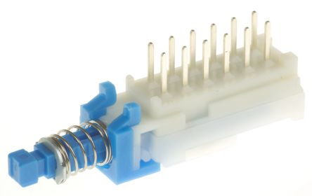
Four Pole Double Throw (4PDT) Latching Push Button Switch, PCB you can find it HERE

Using the 6 Pins of the ESP8266-01
COLOR Code :
-
GPIO0 Back
-
GPIO1 Brown
-
GPIO2 Red
-
GPIO3 Orange
-
GPIO4 Yellow
-
GPIO14 Green
-
Vcc Violet (normaly I use ORANGE for 3.3V)
-
Gnd Blue (and BLACK for GND)
-
Changes made to previous “BLYNK” sketch
add lines to “Settings.h”
/*-------------------------------Virtual Pins---------------------------------*/
  #define vPIN_HX711_WEIGHT       V51
  #define vPIN_HX711_COUNT        V52
  #define vPIN_HX711_RESET        V53     // Reset SCALE to Zero
  #define vPIN_ON_OFF_OLED        V54     // Turn ON/OFF I2C OLED SCALE
mqtt_publish.h
//=============================================TAB 2===========================

//---------------------------------------------SCALE-----(I2C  OLED)-----------
  BLYNK_WRITE(vPIN_ON_OFF_OLED) {    // ON/OFF I2C OLED
    if (param.asInt()) {
      client.publish("Scale01/cmnd/POWER","1");
    } else {
      client.publish("Scale01/cmnd/POWER","0");
    }
  }

  BLYNK_WRITE(vPIN_HX711_RESET) {    // Reset SCALE to Zero
    if (param.asInt()) {
      client.publish("Scale01/cmnd/Sensor34","1");
    }
  }
mqtt_subscribe.h
//=========================================TAB 2=============================================

//------------------------------SCALE--------SENSOR------------------------------------------
// MQT: Scale01/tele/SENSOR =
//{"Time":"2019-05-28T12:42:28","HX711":{"Weight":0.250,"Count":250}}

    }else if (String(topic) == InTOPIC_10) { // Scale01/tele/SENSOR
      StaticJsonBuffer<150> jsonBuffer;
      JsonObject& root = jsonBuffer.parseObject((char*)payload);
        const char* Time = root["Time"];                      // 2019-03-19T13:19:16
             float  Weight = root["HX711"]["Weight"]; // 0.250
                int  Count = root["HX711"]["Count"];  // 250
        Blynk.virtualWrite(vPIN_HX711_WEIGHT,Weight);
        Blynk.setProperty (vPIN_HX711_WEIGHT,"color","#ffff00");  // YELLOW
        Blynk.virtualWrite(vPIN_HX711_COUNT,Count);
        Blynk.setProperty (vPIN_HX711_COUNT,"color","#04C0F8");   // BLYNK_BLUE

    }
  }
“BLYNK” Tasmota Project _# 4
-
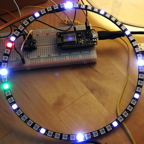
My TASMOTA Clock
HARDWARE
- 4x Ring Wall Clock 15 X Ultra Bright WS2812 5050
- 1x Any ESP Device (NodeMCU, Wemo D1, ESP-01)
- Clock mode (example) Scheme5
-
TASMOTA Clock on a 64 WS2812B pixels panel
| Commands | Parameters |
|---|---|
| — | — |
| Channel<x> |
0..100 = set PWM channel dimmer value from 0 to 100% |
| Color | Show color setting (hex or decimal depending on SetOption17 ) |
r,g,b = set color by decimal value ( 0..255 ) |
|
#CWWW = set hex color value for CT lights |
|
#RRGGBB = set hex color value for RGB lights |
|
#RRGGBBWW = set hex color value for RGBW lights |
|
#RRGGBBCWWW = set hex color value for RGBCCT lights (5 PWM channels) |
|
| Set color to | |
1 = red |
|
2 = green |
|
3 = blue |
|
4 = orange |
|
5 = light green |
|
6 = light blue |
|
7 = amber |
|
8 = cyan |
|
9 = purple |
|
10 = yellow |
|
11 = pink |
|
12 = white (using RGB channels) |
|
+ = next color |
|
- = previous color |
|
| Color2 | Same as Color but adjust to current Dimmer value |
| Color3 |
#RRGGBB = set seconds clock hand hex color value (only in Scheme 5 )
|
| Color4 |
#RRGGBB = set minutes clock hand hex color value (only in Scheme 5 )
|
| Color5 |
#RRGGBB = set hour clock hand hex color value (only in Scheme 5 )
|
| Color6 |
#RRGGBB = set clock hour marker hex color value (only in Scheme 5 )
|
| CT |
153..500 = set color temperature from 153 (cold) to 500 (warm) for CT lights |
+ = increase CT value by 10 |
|
- = decrease CT value by 10 |
|
| Dimmer |
0..100 = set dimmer value from 0 to 100% |
+ = increase by 10 |
|
- = decrease by 10 |
|
| Fade |
0 = do not use fade (default)
|
1 = use fade |
|
| HsbColor |
<hue>,<sat>,<bri> = set color by hue, saturation and brightness |
| HsbColor1 |
0..360 = set hue |
| HsbColor2 |
0..100 = set saturation |
| HsbColor3 |
0..100 = set brightness |
| Led<x> |
#RRGGBB = set Led<x> hex color value where <x> is the pixel number (aplies only to addressable LEDs)
|
| LedTable |
0 = do not use LED gamma correction (default up to 6.5.0.8)
|
1 = use gamma correction (default since 6.5.0.9)
|
|
| Pixels |
1..512 = set amount of pixels in strip or ring and reset Rotation (applies only to addressable LEDs)
|
| Rotation |
<value> = set amount of pixels to rotate (up to Pixels value) (applies only to addressable LEDs)
|
| Scheme | Light effects |
+ = next scheme |
|
- = previous scheme |
|
0 = single color for LED light (default)
|
|
1 = start wake up sequence (same as Wakeup ) |
|
2 = cycle up through colors using Speed option |
|
3 = cycle down through colors using Speed option |
|
4 = random cycle through colors using Speed and Fade |
|
| The following schemes are usable only with addressable LEDs, e.g. WS281X, Neopixel | |
5 = clock mode (example) |
|
6 = candlelight pattern |
|
7 = RGB pattern |
|
8 = Christmas pattern |
|
9 = Hannukah pattern |
|
10 = Kwanzaa pattern |
|
11 = rainbow pattern |
|
12 = fire pattern |
|
| Speed |
1..20 = set fade speed from fast 1 to very slow 20
|
+ = increase speed |
|
+ = decrease speed |
|
| Wakeup | Start wake up sequence from OFF to stored Dimmer value |
0..100 = Start wake up sequence from OFF to provided Dimmer value |
|
| WakeupDuration |
1..3600 = set wake up duration in seconds |
| White |
1..100 = set white channel brightness in single white channel lights (single W or RGBW lights) |
| Width1 |
0..4 = set LED group width (only in Scheme 6 - 12 )
|
| Width2 |
0..30 = set width of the seconds clock hand (only in Scheme 5 )
|
| Width3 |
0..30 = set width of the minutes clock hand (only in Scheme 5 )
|
| Width4 |
0..30 = set width of the hour clock hand (only in Scheme 5 )
|
| See also |
SetOption15 - Set PWM control |
SetOption16 - Reverse Clock Scheme direction |
|
SetOption17 - Show Color string as hex or decimal |
|
SetOption20 - Update of Dimmer/Color/CT without turning power on |
|
SetOption37 - Color remapping for led channels |
Clock 0 - 4 Schemes (Light effects) are available in Home Assistant.
You can Read inputs and Control outputs in “ BLYNK ” app using MQTT.
Good job Pico
Alexis
“BLYNK” Tasmota Project _# 5
-
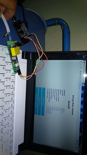
Sonoff POW R2
HARDWARE
- Official Firmware Pictures
- Tasmota Sonoff POW R2 & HA
Message        | Unit | Description
---------------|------|-----------------------------------------------------
TotalStartTime | Date | DateTime of calculation for Total
Total          | kWh  | Total Energy usage including Today
Yesterday      | kWh  | Total Energy usage between 00:00 and 24:00 yesterday
Today          | kWh  | Total Energy usage today from 00:00 until now
Period         | Wh   | Energy usage between previous message and now
Power          | W    | Current effective power load
ApparentPower  | W    | Power load on the cable = sqrt(Power^2 +
               |      | ReactivePower^2)
ReactivePower  | W    | Reactive load
Factor         |      | The ratio of the real power flowing to the load to
               |      | the apparent power in the circuit
Voltage        | V    | Current line voltage
Current        | A    | Current line current
-
How to “Flash TASMOTA on Sonoff POW R2”
-
Based on the 2.5.2 Arduino ESP8266 core
Firmware binary for 4M flash devices only! - This binary will NOT work on 1M flash devices
sonoff-4m.bin
another way to flash the Sonoff POW R2 by sending the bin file using ESPTool.
-
Power Monitoring Calibration
Sonoff Pow R2 might need calibration . See Power Monitoring Calibration
| Command | Parameters |
|---|---|
| AmpRes | Current sensor resolution |
0..3 = maximum number of decimal places |
|
| CurrentHigh |
0 = disable current high threshold (default)
|
<value> = set current high threshold value in miliamps |
|
| CurrentLow |
0 = disable current low threshold (default)
|
<value> = set current low threshold value in miliamps |
|
| CurrentSet |
<value> = calibrate current to target value in mA |
| EnergyRes | Energy sensor resolution |
0..5 = maximum number of decimal places |
|
| EnergyReset | Show Energy Total, Yesterday and Today |
| EnergyReset1 |
0..42500 = (§re)set Energy Today in Wh |
| EnergyReset2 |
0..42500 = (§re)set Energy Yesterday in Wh |
| EnergyReset3 |
0..42500000 = (§re)set Energy Total in Wh |
| FreqRes | Frequency sensor resolution |
0..3 = maximum number of decimal places |
|
| FrequencySet |
<value> = calibrate frequency to a target value in Hz |
| MaxPower |
0 - disable use maximum power monitoring |
<value> = set maximum allowed power in W |
|
| MaxPowerHold |
1 = set default time to 10 seconds to stay over MaxPower before power off |
<value> = set time in seconds to stay over MaxPower before power off |
|
| MaxPowerWindow |
1 = set default time to 30 seconds to stay power off before re-applying power up to 5 times |
<value> = set time in seconds to stay power off before re-applying power up to 5 times |
|
| PowerDelta |
0 = disable reporting on power change |
<value> = set reporting on percentage power change to send an MQTT telemetry message |
|
| PowerHigh |
0 = disable power high threshold (default)
|
<value> = set power high threshold value in W to send an MQTT telemetry message |
|
| PowerLow |
0 = disable power low threshold (default)
|
<value> = set power low threshold value in W to send an MQTT telemetry message |
|
| PowerSet |
<value> = calibrate power to a target value in W |
| Status |
8 = show power usage |
9 = show power thresholds |
|
| VoltageHigh |
0 = disable voltage high threshold (default)
|
<value> = set voltage high threshold value in V |
|
| VoltageLow |
0 = disable voltage low threshold (default)
|
<value> = set voltage low threshold value in V |
|
| VoltageSet |
<value> = calibrate voltage to a target value in V |
| VoltRes | Voltage sensor resolution |
0..3 = maximum number of decimal places |
|
| WattRes | Power sensor resolution |
0..3 = maximum number of decimal places |
|
| See Also |
SetOption21 - Energy monitoring when power is off |
SetOption33 - Configure power monitoring Max_Power_Retry count number |
-
TASMOTA working with Home Assistant
- Showing a complete cycle of my Washing Machine
- Showing 30 minutes .
- Showing last 12 Hrs for my FRIDGE Voltage & Current consumption.
-
Again changes made to previous “BLYNK” sketch
add lines to “Settings.h”
/*-------------------------------Virtual Pins---------------------------------*/

  #define vPIN_MONITOR            V61
  #define vPIN_POWER              V62
  #define vPIN_ENERGY             V63
  #define vPIN_TIME               V64
  #define vPIN_WASHER_ON_OFF      V65
add lines to “mqtt_publish.h”
//=============================================TAB 3============================================

//---------------------------------------------WASHER-------------------------------------------
  BLYNK_WRITE(vPIN_WASHER_ON_OFF) {    // WASHER ON/OFF
    if (param.asInt()) {
      client.publish("Washer/cmnd/POWER","1");
    } else {
      client.publish("Washer/cmnd/POWER","0");
    }
  }
add lines to “mqtt_subscribe.h”
  #define InTOPIC_11         "Washer/tele/SENSOR"
  #define InTOPIC_12         "Washer/stat/POWER"

~

        client.subscribe(InTOPIC_11);
        client.subscribe(InTOPIC_12);

~
//========================================= TAB 3 =====================================

//------------------------------WASHER--------SENSOR---------------------------------------

//MQT: Washer/tele/SENSOR =
//{"Time":"2019-07-02T02:02:30","ENERGY":{"TotalStartTime":"2019-06-30T04:31:57",
//"Total":0.337,"Yesterday":0.117,"Today":0.000,"Period":0,"Power":0,
//"ApparentPower":0,"ReactivePower":0,"Factor":0.00,"Voltage":234,"Current":0.000}}

    }else if (String(topic) == InTOPIC_11) { // Washer/tele/SENSOR
      StaticJsonBuffer<350> jsonBuffer;
      JsonObject& root = jsonBuffer.parseObject((char*)payload);
             float  vol = root["ENERGY"]["Voltage"];
             float  cur = root["ENERGY"]["Current"];
             float  power = root["ENERGY"]["Power"];
             float  apow = root["ENERGY"]["ApparentPower"];
             float  rpow = root["ENERGY"]["ReactivePower"];
             float  pf = root["ENERGY"]["Factor"];
             float  today = root["ENERGY"]["Today"];
             float  yesterday = root["ENERGY"]["Yesterday"];
             float  total = root["ENERGY"]["Total"];
             float  period = root["ENERGY"]["Period"];
       const char*  StartTime = root["ENERGY"]["TotalStartTime"];
       const char*  Time = root["Time"];

        Blynk.setProperty (vPIN_MONITOR, "label",String("\xF0\x9F\x94\x8C")+"Voltage"+"                        "+String("\xE2\x9A\xA1")+"Current"+"                         "+String("\xF0\x9F\x94\x8B")+"Power");
        Blynk.virtualWrite(vPIN_MONITOR, (String (vol,1)+" V      "+String (cur,3)+" A      "+String(power,1)+" W   "));
        Blynk.setProperty (vPIN_POWER, "label",String(String("\xE2\x9A\xA1")+"Power Factor"+"          "+String("\xE2\x9A\xA1")+"Apparent Power"+"         "+String("\xE2\x9A\xA1")+"Reactive Power"));
        Blynk.virtualWrite(vPIN_POWER, (String (pf,2)+"            "+String (apow,1)+" VA        "+String (rpow,1)+" VAr   "));
        Blynk.setProperty (vPIN_ENERGY, "label",String("\xE2\x9A\xA1")+"ENERGY Today"+"            "+String("\xE2\x9A\xA1")+"ENERGY Yesterday"+"            "+String("\xE2\x9A\xA1")+"ENERGY Total");
        Blynk.virtualWrite(vPIN_ENERGY, (String (today,3)+"       "+String (yesterday,3)+"       "+String(total,3)+"  kWh  "));
        Blynk.setProperty (vPIN_TIME, "label",String("\xE2\x8C\x9A")+"Time"+"                                  "+String("\xE2\x9A\xA1")+"TotalStartTime"+"                     "+String("\xE2\x9A\xA1")+"Period"+"   ");
        Blynk.virtualWrite(vPIN_TIME, (String (Time)+"    "+String (StartTime)+"    "+String (period,1)+"    "));

//------------------------------WASHER--------POWER------------------------------------------
    }else if (String(topic) == InTOPIC_12) { // Washer/stat/POWER
      StaticJsonBuffer<250> jsonBuffer;
      JsonObject& root = jsonBuffer.parseObject((char*)payload);
        if ((char)payload[1] == 'N') {
          Blynk.virtualWrite(vPIN_WASHER_ON_OFF,1);
        }else{
          Blynk.virtualWrite(vPIN_WASHER_ON_OFF,0);
        }


    }
  }

//=========================================================================================
- (again) same results was accomplished before for Sonoff S31 using Node-Red
- In “BLYNK” app. many buttons can be added as:
- VoltageHigh & VoltageLow threshold value.
- CurrentHigh & CurrentLow threshold value.
- MaxPower, MaxPowerHold & MaxPowerWindow how to stay over MaxPower before power off.
- PowerHigh & PowerLow to send an MQTT telemetry message.
- EnergyReset1, EnergyReset2 & EnergyReset3 to set or reset Energy Values.
Congratulations I used the QR code to load the project. You could kindly share the integral code with the links, I am very grateful.
As you can see with a Nodemcu with FW Tasmota 6.5 and with my PZEM-004T V3, I was able to correctly visualize the electrical energy measurement. Now I would like to see what Blynk did like you did, but I wouldn’t know how to do it if you could help me. Thank you so much .
Ok ok I’ll read it right and see if we understand something. But did you use Version 1 or Version 3 of the PZEM004T to make the energy meter? Thank you very much for answering me
To RESET ENERGY in Tasmota
Open “Console Menu” then
Type:
EnergyReset1 0 - to reset Energy Today
EnergyReset2 0 - to reset Energy Yesterday
EnergyReset3 0 - to reset Energy Total & Total Start Time
| Command | Parameters |
|---|---|
| EnergyReset1 |
0..42500 = (§re)set Energy Today in Wh |
| EnergyReset2 |
0..42500 = (§re)set Energy Yesterday in Wh |
| EnergyReset3 |
0..42500000 = (§re)set Energy Total in Wh |
-
Something IMPORTANT I need to add :
All libraries (Ver.) I used in my BLYNK scketchs are the same Libraries selected by TASMOTA
  #include <ESP8266WiFi.h>
  #include <ESP8266mDNS.h>
  #include <WiFiUdp.h>
  #include <ArduinoOTA.h>
  #include <PubSubClient.h>
  #include <ArduinoJson.h>
- ArduinoJson-5.13.4 …( this is V5 and not V6 . if you are using V6 it will not work)
- PubSubClient-EspEasy-2.7.12


