Updated 28/03/2018:
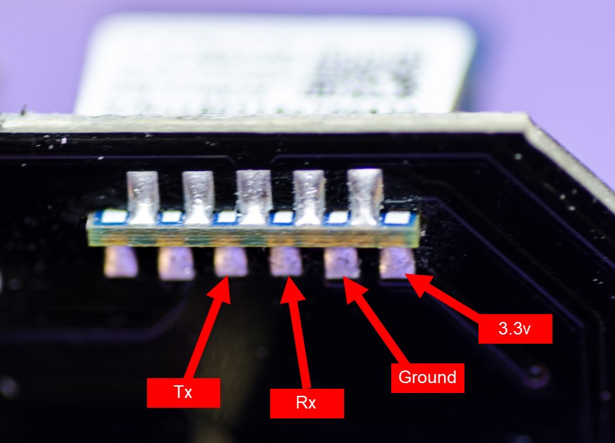
The picture I’d originally posted had the wrong solder pad labelled as the Tx pin.
Many thanks to Michael Harwerth for pointing this out. The photo below is now correct.
I’ve been using Sonoff S20’s for a while, both at home in the UK and at our holiday home in Spain. The one thing I don’t like about them is their size and the position of the physical button.
I came across these on eBay recently and decided to order one and have a play with it:
[Updated link, as the previous one was deleted]
They’re about 20% more expensive than the S20, and I’ve only been able to find them with the EU (Type F) style of fitting. They’re also a bit more difficult to make the electrical connections for flashing them the first time around, but they are considerably smaller than the S20 and the physical switch is in a better position in my opinion.
Here’s what they look like side by side:
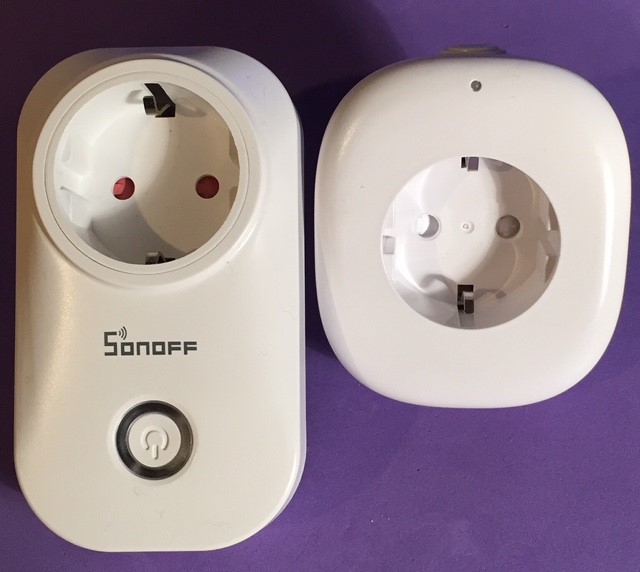
The new sockets don’t seem to have a brand name. The info printed on the box calls it a “WiFi Smart Socket W-DE004” but they’re being sold on AliExpress under the names Rondaful and Xingg. Surprisingly, they are cheaper on eBay at the moment.
The instructions claim CE and RoHS compliance, but there are no compliance marks on the device itself, so you can draw your own conclusions from that.
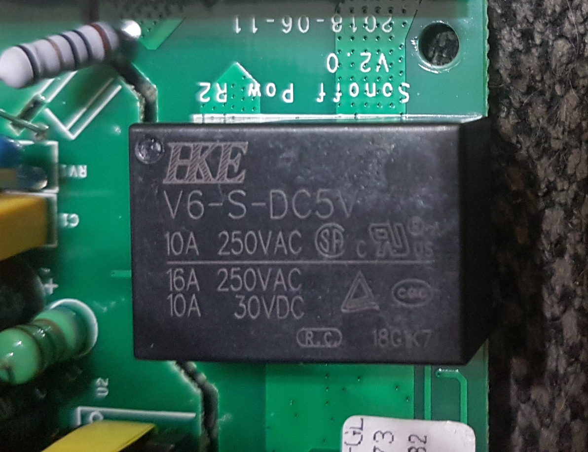
The relay claims to be rated at 10A @ 250VAC, but I don’t think I’d want to put that much current through it (but the same also applies to the S20).
There is also a USB socket on the bottom which is said to provide 2.1A max @ 5V. This isn’t switched on and off by the relay, which makes sense if you want to use it for charging a phone etc.
There’s App that claims to have functionality including timers and Amazon Alexa, Google Home and IFTTT support, but I’ve not tried it.
When the Smart Socket arrived I was hoping that I’d be able to re-flash the firmware via the USB socket on the bottom, but no such luck, so I set about ripping it apart…
You have to remove a plastic cap which sits between the prongs, and I found that the easiest way to do this was to drill a hole in the middle of the cap and use a small screwdriver to lever it out. I’ve not bothered replacing mine, but you could patch-up the hole and refit it if you wanted.
Once removed, two screws are exposed:

When these are removed the front cover lifts off and the circuit board is exposed:

There’s another screw to remove which then allows the circuit board to be eased forwards enough to allow you to get to the small daughter-board that the ESP8266 sits on. Take note of how the switch button is located so you can refit it afterwards.
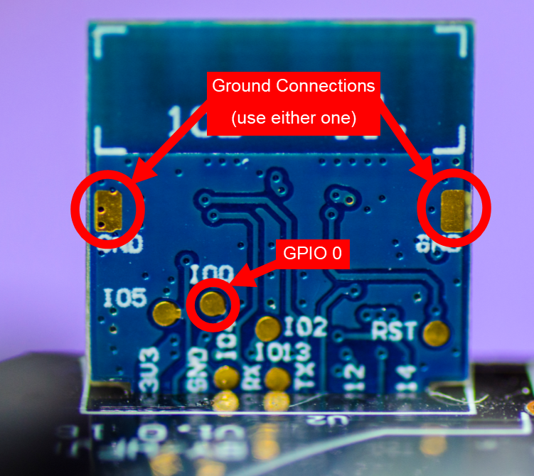
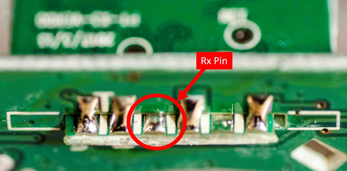
Unfortunately, the manufacturers haven’t made life easy when it comes to accessing the pins necessary to re-flash the firmware. There’s no 4-pin header and not even anywhere to solder your own in place. The Tx and GPIO 0 connections are fairly easy to access:
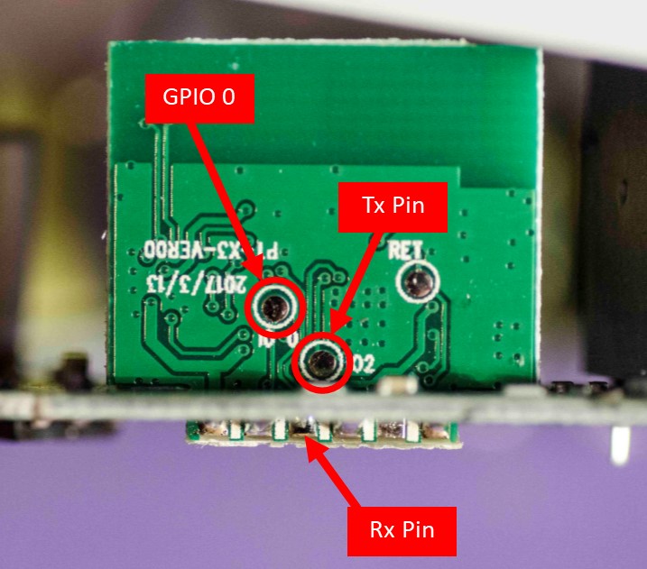
but the Rx connection is a bit trickier:
I chopped-up a couple of breadboard patch cables and soldered one end on to the Tx and Rx connections (don’t forget that you connect Tx to the Rx connection on your FTDI programmer and vice-versa).
Hopefully it goes without saying, but DO NOT CONNECT THE SMART SOCKET TO THE MAINS WHEN YOU’RE RE-FLASHING THE FIRMWARE. @marvin7 this means you too! 
I powered the Smart Socket through the USB socket on the bottom, using a USB-A to USB-A Male-to-Male cable. If you don’t have one of these lying around then it’s easy to make one by cutting-up a couple of old USB cables.
To reprogram the device the GPIO 0 connection needs to be shorted to Ground when you apply the 5V power via the USB socket. Once the power has been applied the GPIO 0 to Ground connection can be removed. I used the metal casing of the USB socket as a convenient Ground connection point.
Powering the Smart Socket this way means you don’t have to use the power connection on your FTDI programmer. In theory you should connect the Ground wire from the FTDI to the Ground of the Smart Socket, but as both were connected directly to my PC via USB, I found this wasn’t necessary in my case.
Settings for re-flashing the device using the Arduino IDE with ESP8266 Core installed are documented in the code below. Once the device has been re-flashed and tested (don’t forget to remove and re-apply the USB power first, to power -cycle the ESP after re-flashing) you can de-solder the wires that you connected to Tx, Rx and GPIO 0 then re-assemble. It’s easier to get the button for the physical switch back in place if you hold the socket upside down then you’re refitting the main circuit board.
Using OTA to re-flash the firmware for future upgrades is obviously the way to go, as you wouldn’t want to be disassembling and re-soldering the connections unless you really have no choice.
The Smart Socket uses the following GPIO pins:
GPIO 14 Relay (Active High)
GPIO 13 Blue LED (Active Low)
GPIO 1 Physical Switch (Low when activated)
Because GPIO 1 is also the Tx pin on the ESP8266 it means that you can’t use the serial interface for debugging.
Here’s a simple Blynk sketch that incorporates OTA for future updates.
It’s designed to default to having the connected device switched off after a power outage, for safety reasons. If you want to sync with the previous state as held on the Blynk server instead then it’s a fairly simple modification for you to make.
I haven’t built-in any non-blocking code for the Wi-Fi/Blynk connection, so the physical switch won’t work if you can’t connect to the Blynk server. Once again, this is fairly easy to get around if you feel like tweaking the code.
// Blynk + OTA Code for "W-DE004 WIFI SMART SOCKET" by Pete Kniight

// Arduino IDE Upload Settings
// Board:            "Generic ESP8266 Module"
// Flash Mode:       "DOUT"
// Flash Size:       "1M (No SPIFFS)"
// Debug Port:       "Disabled"
// Debug Level:      "None"
// IwIP Variant:     "v1.4 Prebuilt"
// Reset Method:     "ck"
// Crystal Frequency "26 MHz"
// Flash Frequency:  "40 MHz"
// CPU Frequency:    "80MHz"
// Upload Speed:     "115200"

// Blynk App Project Setup:
// Add a Button widget connected to Virtual Pin V1
// Set button widget to Switch mode

// Notes:
// The wifi socket uses GPIO1 for the physical button. This is the hardware TX pin on the ESP8266, so SERIAL OUTPUT FOR DEBUGGING WILL NOT WORK !
// Please do not add Serial.begin() to this sketch !!


#include <ArduinoOTA.h>
#include <ESP8266WiFi.h>
#include <BlynkSimpleEsp8266.h>
#include <Ticker.h>                  // Used to flash the LED in non-blocking mode

char auth[] = "xxxxxxxx";
char ssid[] = "xxxxxxxx";
char pass[] = "xxxxxxxx";
char OTAhost[] = "xxxxxxxx";


#define RELAY1    14                 // Wi-Fi Switch relay is connected to GPIO 14 (LOW(0)=0ff, HIGH(1)=On)
#define buttonPin  1                 // Wi-Fi Switch pushbutton is connected to GPIO 1 (LOW(0)=Pushed, HIGH(1)=Released)
#define BlueLED   13                 // Wi-Fi Switch Blue LED is connected to GPIO 13 (LOW(0)=0n, HIGH(1)=Off)

int RELAY1_State;                    // Used to track the current Relay state
int reading = HIGH;                  // Used in the switch debounce routine
int buttonState=HIGH;                // The current button state is released (HIGH)
int lastButtonState = HIGH;          // The last button state is also relesed (HIGH) - Used in debounce routine
unsigned long lastDebounceTime = 0;  // The time in Millis that the output pin was toggled - Used in debounce routine
unsigned long debounceDelay = 20;    // The debounce delay; increase if you get multiple on/offs when the physical button is pressed

Ticker blueticker;                   // Create and instance of Ticker called blueticker
BlynkTimer timer;                    // Create and instance of BlynkTimer called timer


void setup()
{
  pinMode(RELAY1, OUTPUT);
  pinMode(BlueLED, OUTPUT);
  pinMode(buttonPin, INPUT);

  digitalWrite(RELAY1, LOW);                // Turn the Relay off
  digitalWrite(BlueLED, HIGH);              // Turn the Blue LED off

  blueticker.attach(0.1, bluetick);         // start blueticker with 0.1 second flashes to indicate we're trying to connect to WiFi/Blynk
  WiFi.mode(WIFI_STA);
  Blynk.begin(auth, ssid, pass);
  while (Blynk.connect() == false) {}       // Dont proceed until we're connected to WiFi/Blynk
  blueticker.detach();                      // Stop the blueticker now we're connected
  digitalWrite(BlueLED, HIGH);              // Turn the Blue LED Off if it was previoulsy On

  Blynk.virtualWrite(V1, 0);                // If the App switch widget is On, turn it Off

  ArduinoOTA.onError([](ota_error_t error) { ESP.restart(); });
  ArduinoOTA.setHostname(OTAhost);
  ArduinoOTA.begin();

  timer.setInterval(10L, CheckButtonState); // Timer to check the physical button every 10ms
}


void loop()
{
  Blynk.run();
  ArduinoOTA.handle();
  timer.run();
}


BLYNK_WRITE(V1)                             // This code is triggered when the App button state changes
{
  int pinValue = param.asInt();             // Assign incoming value from pin V1 to a variable

  if (pinValue==1)                          // Do this if it was an On command from the Button widget in the App
  {
    digitalWrite(RELAY1, HIGH);             // Turn the relay On
    RELAY1_State = HIGH;                    // Keep track of the relay state
    digitalWrite(BlueLED, LOW);             // Turn the LED On
  }
  else                                      // Else do this if it was an Off command from the Button widget in the App
  {
    digitalWrite(RELAY1, LOW);              // Turn the relay Off
    RELAY1_State = LOW;                     // Keep track of the relay state
    digitalWrite(BlueLED, HIGH);            // Turn the LED Off
  }
}


void bluetick() // Non-blocking ticker for Blue LED
{
  //toggle state
  int state = digitalRead(BlueLED);         // get the current state of the BlueLED pin
  digitalWrite(BlueLED, !state);            // set pin to the opposite state
}


void CheckButtonState()
{
  reading = digitalRead(buttonPin);         // read the state of the physical switch
  if (reading != lastButtonState)
  {
    lastDebounceTime = millis();            // Start the debounce timer
  }

  if ((millis() - lastDebounceTime) > debounceDelay)
  {
    if (reading != buttonState)             // We get here if the physical button has been in the same state for longer than the debounce delay
    {
      buttonState = reading;

      if (buttonState == LOW)               // only toggle the power if the new button state is LOW (button pressed)
      {
        RELAY1_State = !RELAY1_State;
        if (RELAY1_State==HIGH)             // The physical button press was an instruction to turn the power On
        {
          digitalWrite(RELAY1, HIGH);       // Turn the relay On
          digitalWrite(BlueLED, LOW);       // Turn the LED On
          Blynk.virtualWrite(V1, 1);        // Turn the App button widget On
        }
        else                                // The physical button press was an instruction to turn the power Off
        {
          digitalWrite(RELAY1, RELAY1_State);  // Turn the relay Off
          digitalWrite(BlueLED, HIGH);         // Turn the LED Off
          Blynk.virtualWrite(V1, 0);           // Turn the App button widget Off
        }
      }
    }
  }
  lastButtonState = reading;                // Update lastButtonState for use next time around the loop
}
I should add that I don’t normally run Blynk code like this on my devices, I use MQTT and Node-Red to achieve my Blynk connectivity so this has just been bodged together as a quick and dirty example of how to use these Smart Sockets with Blynk. Any constructive criticism and improvements for the benefit of others are welcome, but the code isn’t something I’ll be spending any more time on.
I’ve been using one of these Smart Switches for a couple of weeks now (using my MQTT code) to switch a lamp on and off at scheduled times and it’s working just as well as the S20 that it replaced.
I like the smaller physical size and the fact that the cable doesn’t obstruct access to the physical switch. They look more discreet than the S20 when plugged-in to a wall socket and are easier to use with multi-way adapters as they don’t block the other sockets as badly as the S20.
I’d planned to buy more S20’s for our place in Spain, so I’ve ordered some more of these instead. I’m still hoping to find some with UK fittings as well, but I’ve not had any joy so far. If anyone comes-up with a source for the UK version then please let me know.
Pete.