#11 - The simple, but mystifyingly complex, Bridge
The Bridge is meant to allow totally separate projects to share data, and/or control things between themselves. You can also have just one project with multiple devices, but have any of the 1st device’s Blynk functions triggered directly by Bridge code in the 2nd device… bypassing the App.
As long as the Auth tokens were generated on the same server, then this can even share between different accounts… I think? 
Basically, Blynk Bridge is a way of emulating a receiving device’s App input, triggering a Physical Pin or Virtual Pin (using a BLYNK_WRITE() function), but the triggering action came from another transmitting device’s code, not the App… say all that five times fast 
OK, here is a simple bidirectional Bridge network between two identical sketches/devices… (does not have to be identical, but this is for demonstration  )
)
This example has two projects/devices. On each project you can toggle the ‘Local’ project’s device’s LED with Button V0 or the ‘remote’ project’s device’s LED with Button V1… and visa versa.
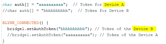
NOTE for each device’s sketch, comment out the Upper OR Lower AUTH and Bridge tokens, depending on which project you are flashing this sketch to.
For example… use these top settings for Project/device A, and the bottom ones for Project/device B
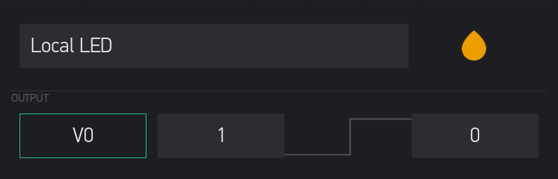
For the App projects, simply add in two buttons, Local LED (V0) and Remote LED (V1) for each project.
*** Don’t forget to add in the Bridge Widget to each project that sends data to another
Also, when using Built In LED’s they are usually triggered LOW, so to make that make visual sense, simply reverse each Button’s settings as such…
#include <ESP8266WiFi.h>
#include <BlynkSimpleEsp8266.h>

char auth[] = "aaaaaaaaaa";  // Token for Device A
//char auth[] = "bbbbbbbbbb";  // Token for Device B

char ssid[] = "xxxxxxxxxx";
char pass[] = "xxxxxxxxxx";
//char server[] = "xxx.xxx.xxx.xxx";  // IP for your Local Server
char server[] = "blynk-cloud.com";  // URL for Blynk Cloud Server
int port = 8080;
#define DeviceLED 2 // Built in LED for Wemos or NodeMCU v3, Or 16 for NodeMCU v1

WidgetBridge bridge1(V127); //  Initiating Bridge Widget on V127 (this is just as holding pin for the bridge, can be any unused vPin and each bridge needs its own)


void setup() {
  pinMode(DeviceLED, OUTPUT);
  WiFi.begin(ssid, pass);
  Blynk.config(auth, server, port);
  Blynk.connect();
}


BLYNK_CONNECTED() {
  bridge1.setAuthToken("bbbbbbbbbb"); // Token of the Device B
  //bridge1.setAuthToken("aaaaaaaaaa"); // Token of the Device A
}


BLYNK_WRITE(V0) { // Local LED
  digitalWrite(DeviceLED, param.asInt()); // take the state of the Button and send it to the Local LED
}


BLYNK_WRITE(V1) { // Remote LED
  bridge1.virtualWrite(V0, param.asInt()); // take the state of the Button and send it to the Remote LED
}
This concept is completely upgradable to anything else you want to control via Bridge.
NOTE: When using Blynk Functions on the receiving side, you MUST have a widget for the receiving vPin in that devices project… just use the same vPin for both the Blynk Function and the Widget’s Blynk.virtualWrite() command…
Sending Project…
void MEGAupdate() { //  Timed Function
  bridge1.virtualWrite(V43, t);  // Solar DHT22 Temperature to receiving project
  bridge1.virtualWrite(V44, h);  // Solar DHT22 Humidity to receiving project
  bridge1.virtualWrite(V47, current_mA);  // Solar Panel Current to receiving project
  bridge1.virtualWrite(V48, busvoltage);  // Solar Battery Voltage to receiving project
}
Receiving Project…
BLYNK_WRITE(V43) { // Solar DHT22 Temperature from sending project
  Blynk.virtualWrite(V43, param.asFloat());
}

BLYNK_WRITE(V44) { // Solar DHT22 Humidity from sending project
  Blynk.virtualWrite(V44, param.asFloat());
}

BLYNK_WRITE(V47) { // Solar Panel Current from sending project
  Blynk.virtualWrite(V47, param.asFloat());
}

BLYNK_WRITE(V48) { // Solar Battery Voltage from sending project
  Blynk.virtualWrite(V48, param.asFloat());
}
NOTE: When initiating the bridges, you can use any name and available (unused) vPin on the “transmitter” project’s side… but each separately defined bridge (AKA for seperate MCUs) does need a different vPin.
These "holding’ vPins are NOT the same as whatever vPins you are trying to control on the receiving side… so there is NO need to make them the same unless you really like it that way…
For example…
WidgetBridge MyNodeMCU(V125); //  Initiating Bridge Widget on V125 (this is just as holding pin for the bridge, can be any unused vPin and each bridge needs its own)

WidgetBridge MyWemos(V126); //  Initiating Bridge Widget on V126 (this is just as holding pin for the bridge, can be any unused vPin and each bridge needs its own)

WidgetBridge MyUNO(V127); //  Initiating Bridge Widget on V127 (this is just as holding pin for the bridge, can be any unused vPin and each bridge needs its own)
BLYNK_CONNECTED() {
  MyNodeMCU.setAuthToken("AuthToken of NodeMCU"); // Token of the hardware A
  MyWemos.setAuthToken("AuthToken of Wemos"); // Token of the hardware B
  MyUNO.setAuthToken("AuthToken of UNO"); // Token of the hardware C
}
BLYNK_WRITE(V0) {
  MyNodeMCU.virtualWrite(V3, param.asInt()); // take the state of this transmitting MCU's virtual V0 button and send it to the receiving MCU's V3 vPin
}

BLYNK_WRITE(V1) {
  MyWemos.virtualWrite(V8, param.asInt()); // take the state of this transmitting MCU's virtual button on V1 and send it to the receiving MCU's V8 vPin
}

BLYNK_WRITE(V2) {
  MyUNO.digitalWrite(13, param.asInt()); // take the state of this transmitting MCU's virtual button on V2 and send it to the receiving MCU's GPIO13
}