PZEM-004T v3.0 and NodeMCU / Wemos Mini running on Blynk - How To procedure

+ =

Hello,

The purpose of this project is to have PZEM-004T v3.0 connect to NodeMCU or Wesmo Mini D1 to display data on the Blynk app. (using local Blynk server)

This project is cheap to make and fun to build.
PZEM cost $4.33 (AliExpress)
Wemos D1 cost $2.3 (Ebay)

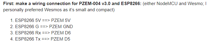
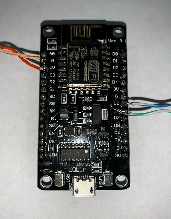
First: make a wiring connection for PZEM-004 v3.0 and ESP8266: (either NodeMCU and Wesmo; I personally preferred Wesmos as it’s small and compact)

  1. ESP8266 5V ==> PZEM 5V
  2. ESP8266 G ==> PZEM GND
  3. ESP8266 Rx ==> PZEM D6
  4. ESP8266 Tx ==> PZEM D5

Second: make a AC Voltage wiring connection: (Warning: you are dealing with high voltage that can kill you, so be extra careful with this as I have no responsibility for this)
See product manual for AC voltage wiring connection

Third: Download Blynk App to your phone, create new project and generate an Authorization code

Fourth: Program the ESP8266

  1. Create a new project; download and paste the below code to your Arduino project: (make sure to update your WiFI SSID, WiFi password; Blynk app authorization key)
#include <ArduinoOTA.h>
#include <BlynkSimpleEsp8266.h>
#include <SimpleTimer.h>
#include <ModbusMaster.h>
#include <ESP8266WiFi.h>
#include "settingsPZEM.h"

#include <SoftwareSerial.h>  //  ( NODEMCU ESP8266 )
SoftwareSerial pzem(D5,D6);  // (RX,TX) connect to TX,RX of PZEM for NodeMCU
//SoftwareSerial pzem(D7,D8);  // (RX,TX) connect to TX,RX of PZEM
#include <ModbusMaster.h>
ModbusMaster node;
SimpleTimer timer;

//WiFi data
char ssid[] = "Put your WiFi SSID here";                    //WiFi Credential
char pass[] = "Put your WiFi password here";              //WiFi Password
char server[] = "Put your Blynk local server IP address here";         //Blynk local server IP address
int port = 8080;                        //Blynk local port
#define USE_LOCAL_SERVER                //Use local Blynk Server - comment-out if use Blynk hosted cloud service
#define AUTH    "put your Blynk App Authorization code here"    //PZEM-004v3 Auth code for Blynk Local Server

int timerTask1;
double U_PR, I_PR,  P_PR,  PPR, PR_F, PR_PF, PR_alarm;
uint8_t result;  uint16_t data[6];


void setup(){
  Serial.begin(115200); Serial.println("Start serial"); pzem.begin(9600); Serial.println("Start PZEM serial");
node.begin(1, pzem);  Serial.println("Start PZEM"); // 1 = ID MODBUS

WiFi.mode(WIFI_STA);
#if defined(USE_LOCAL_SERVER)
  WiFi.begin(ssid, pass);
  Blynk.config(AUTH, server, port);
#else
  Blynk.begin(AUTH, ssid, pass);
#endif
  while (Blynk.connect() == false) {}
  ArduinoOTA.setHostname(OTA_HOSTNAME);
  ArduinoOTA.begin();

//  timerTask1 = timer.setInterval(1000, updateBlynk);

}

void updateBlynk() {
  Blynk.virtualWrite(vPIN_VOLTAGE,               U_PR);
  Blynk.virtualWrite(vPIN_CURRENT_USAGE,         I_PR);
  Blynk.virtualWrite(vPIN_ACTIVE_POWER,          P_PR);
  Blynk.virtualWrite(vPIN_ACTIVE_ENERGY,         PPR);
  Blynk.virtualWrite(vPIN_FREQUENCY,             PR_F);
  Blynk.virtualWrite(vPIN_POWER_FACTOR,          PR_PF);
  Blynk.virtualWrite(vPIN_OVER_POWER_ALARM,      PR_alarm);
}

void loop(){
Blynk.run();
//ArduinoOTA.handle();
//timer.run();

result = node.readInputRegisters(0x0000, 10);
  if (result == node.ku8MBSuccess)  {
U_PR      = (node.getResponseBuffer(0x00)/10.0f);
I_PR      = (node.getResponseBuffer(0x01)/1000.000f);
P_PR      = (node.getResponseBuffer(0x03)/10.0f);
PPR       = (node.getResponseBuffer(0x05)/1000.0f);
PR_F      = (node.getResponseBuffer(0x07)/10.0f);
PR_PF     = (node.getResponseBuffer(0x08)/100.0f);
PR_alarm  = (node.getResponseBuffer(0x09));  
 } 

    Serial.print("U_PR:     "); Serial.println(U_PR);   // V
    Serial.print("I_PR:     "); Serial.println(I_PR,3);   //  A
    Serial.print("P_PR:     "); Serial.println(P_PR);   //  W 
    Serial.print("PPR:      "); Serial.println(PPR,3);   // kWh
    Serial.print("PR_F:     "); Serial.println(PR_F);    // Hz
    Serial.print("PR_PF:    "); Serial.println(PR_PF);  
    Serial.print("PR_alarm: "); Serial.println(PR_alarm,0);
Serial.println("====================================================");

updateBlynk();
  delay(1000);
}
  1. Setting.h: Download the code below to your project and save it as “settingsPZEM.h” (make sure both project_name.ino and settingsPZEM.h are in the same folder location)
//#include <wifi_credentials.h>
// Remove below 2 lines when use Blynk hosted server, 
//#define USE_LOCAL_SERVER       
//#define SERVER                          IPAddress(192,168,1,20)
/*
  Over The Air Hostname  
*/
#define OTA_HOSTNAME                    "PZEM-004v3"
/*
   Virtual Pins - Base
*/
#define vPIN_VOLTAGE		            V0
#define vPIN_CURRENT_USAGE          V1
#define vPIN_ACTIVE_POWER           V2
#define vPIN_ACTIVE_ENERGY          V3
#define vPIN_FREQUENCY              V4
#define vPIN_POWER_FACTOR           V5
#define vPIN_OVER_POWER_ALARM       V6

/*
   Debug. Change to 0 when you are finished debugging.
*/
const int debug             =           1; 
/*
   
*/
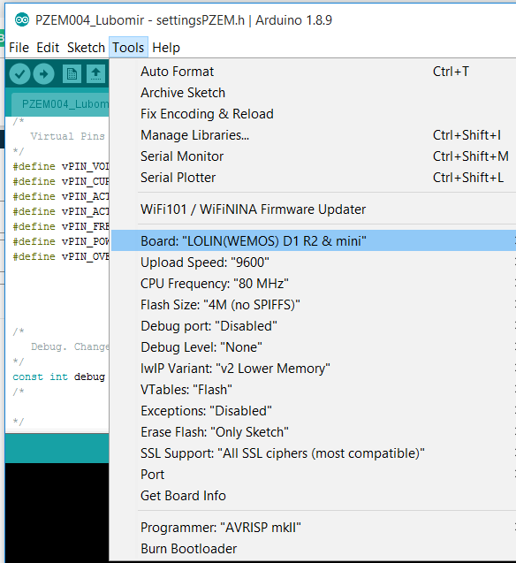
  1. Upload project: From Arduino, save the project and upload it to PZEM004 (make sure the Arduino set to the correct COM port with correct board as shown below)

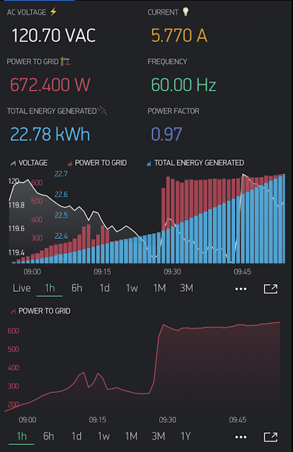
  2. Blynk App: Go to Blynk app on your phone and layout the blynk project with virtual pin number according to the settings.h above.
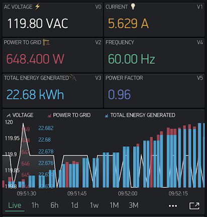
    image

  3. Run and Enjoy:

6 Likes


Could this damage esp8266 pin. 5V vs 3V3?

In theory yes, you should use a level shifter, but in practice ESP8266/NodeMCUs are 5v tolerant on the logic level pins.
However, what you shouldn’t do is to try applying 5v to the pin labelled 3.3v

Pete.

1 Like

7 posts were split to a new topic: Want to use PZEM controller to detect current flow direction

A post was split to a new topic: Energy question

hello,
please, i want help i have pzem-004t v3.0 and nodemcu esp8266. my project is monitor of voltage, current, power and energy.
i go same procedure above but i face problem in "#include “settingsPZEM.h” show settingsPZEM.h: No such file or directory.

[Unformatted code removed by moderator]

@MAZIN2020 I’ve previously explained to you how to format code when you post it to the forum, using triple backticks. You can’t replace the triple backticks with random characters if your choice, it doesn’t work.
Here’s a reminder of what triple backticks look like when you need to copy and paste them in future:

The compilation message you’re receiving is because you didn’t follow the instructions in step 2 of the initial post of this topic.

Pete.

Hello everyone!! This is my first post in this forum!!

I’m new in working with microcontollers (Arduino IDE, Blynk, ESP-IDF, etc) and I’m trying to make the same project using an esp32 (esp32 devkit v1) and a PZEM-004T v3.0, and I have questions about it.

  • The project is using SofwareSerial, and I’ asking myself (and you, of course) if it’s better to use HardwareSerial (I read it’s faster and it needs less cpu than SoftwareSerial)
  • Also, I think it would be an improvement to the project if we can add the features of Power Reset and Alarm Set for the PZEM. ¿Someone knows how could be these coded? I took a look in a PZEM004Tv30 library from mandulaj and I think it’s possible but I don’t know (yet) how to proceed.

Nowadays I’m waiting for a level shifter (5v to 3,3v) in order to mount all the project, but meanwhile, I would like to clarify all the code I will need in order to flash the esp32.

Of course!
SoftwareSerial is used with boards that only have one hardware UART, to enable debugging and interfacing with other hardware at the same time. As your ESP32 has two hardware UARTs you could use one of these instead of the SoftwareSerial port.

Don’t bother, it’s not necessary. ESP32s are 5v tolerant on their logic pins.

Pete.

Thanks for your answers PeteKnight!!

I would like to try to run as soon as possible this project, and then, I will try to add the new features (Power Reset and Alarm Set). I think I need to modify the settingsPZEM.h for that.

Regards.
PS. Sorry about my English, I’m from Spain.

Hi Pete

Following your instructions (or maybe no correctly), i encountered two issues that prohibit the sketch, from compiling.
The fist being ‘’’#include <SimpleTimer.h>’’’ unless i comment this line out, the sketch will not compile.
The second is related to the first line of code in settingsPZEM.h ‘’’//#include <wifi_credentials.h>’’’. If i comment this code in (with my wifi credentials) the compiling error = “wifi_credentials.h”: no such file or directory.
Any guidance appreciated
Thanks

  1. install the simpletimer library, or switch to using BlynkTimer.
  2. re-read thee original post, especially the bit that tells you how and where to create the settings.h file.

Pete.

Well that will be because you’ve modified the original code by adding the line:

#define SimpleTimer BlynkTimer

If you want to use BlynkTimer rather than SimpleTimer then delete the above line along with this one:

#include <SimpleTimer.h>

and replace this line:

SimpleTimer timer;

with

BlynkTimer timer;

Pete.

Hi Pete
i uploaded the sketch to my ESP8266. Pzem Rx to ESP8266 D6 , PZEM Tx to ESP8266 D5
i follow the instruction and copy pasted the code…When running the Serial Monitor, It display 0 no reading.

Have you changed the code at all?

I assume that you’ve connected-up the current transformer, and have just one wire of your mains supply passing through it?

If so, then I’d suggest you check the rest of your wiring.

There are issues with the SoftwareSerial library and more recent versions of the ESP Core (and BTW, your screenshot shows an error message associated with the ESP Core). There are versions of the SoftwareSerial library that are designed for use with the ESP8266, called things like ESP8266SoftwareSerial, it might be worth switching to one of these.

Edited to add - please don’t keep posting screenshots, it’s much better if you copy and paste, and use triple backticks where appropriate.

Pete.

hy sir…
my pzem cant read the current, can you help me.?? this is my code…

/* Comment this out to disable prints and save space */
#define BLYNK_PRINT Serial

/* Untuk Pzem004T */
#include <ArduinoOTA.h>
#include <SimpleTimer.h>
#include <ModbusMaster.h>
#include "settingsPZEM.h"

#include <SoftwareSerial.h>  //  ( NODEMCU ESP8266 )
SoftwareSerial pzem(D5,D6);  // (RX,TX) connect to TX,RX of PZEM for NodeMCU
//SoftwareSerial pzem(D7,D8);  // (RX,TX) connect to TX,RX of PZEM
ModbusMaster node;
SimpleTimer timer;

#include <ESP8266WiFi.h>
#include <BlynkSimpleEsp8266.h>

// You should get Auth Token in the Blynk App.
// Go to the Project Settings (nut icon).
char auth[] = "myauth";

// Your WiFi credentials.
// Set password to "" for open networks.
char ssid[] = "myssid";
char pass[] = "mypass";

int timerTask1;
double U_PR, I_PR,  P_PR,  PPR, PR_F, PR_PF, PR_alarm;
uint8_t result;  uint16_t data[6];

void setup()
{
  // Debug console
  Serial.begin(115200);
//PZEM Serial
  Serial.println("Start serial"); 
  pzem.begin(9600); 
  Serial.println("Start PZEM serial");
  node.begin(1, pzem);  
  Serial.println("Start PZEM"); // 1 = ID MODBUS

  WiFi.mode(WIFI_STA);
  Blynk.begin(auth, ssid, pass);
  while (Blynk.connect() == false) {}
  ArduinoOTA.setHostname(OTA_HOSTNAME);
  ArduinoOTA.begin();

 //timerTask1 = timer.setInterval(3000, updateBlynk);

}

void updateBlynk() {
  Blynk.virtualWrite(vPIN_VOLTAGE,               U_PR);
  Blynk.virtualWrite(vPIN_CURRENT,               I_PR);
  Blynk.virtualWrite(vPIN_ACTIVE_POWER,          P_PR);
  Blynk.virtualWrite(vPIN_ACTIVE_ENERGY,         PPR);
  Blynk.virtualWrite(vPIN_FREQUENCY,             PR_F);
  Blynk.virtualWrite(vPIN_POWER_FACTOR,          PR_PF);
  Blynk.virtualWrite(vPIN_OVER_POWER_ALARM,      PR_alarm);
}

  
  // You can also specify server:
  //Blynk.begin(auth, ssid, pass, "blynk-cloud.com", 80);
  //Blynk.begin(auth, ssid, pass, IPAddress(192,168,1,100), 8080);


void loop()
{
  Blynk.run();
  // You can inject your own code or combine it with other sketches.
  // Check other examples on how to communicate with Blynk. Remember
  // to avoid delay() function!
result = node.readInputRegisters(0x0000, 10);
  if (result == node.ku8MBSuccess)  {
U_PR      = (node.getResponseBuffer(0x00)/10.0f);
I_PR      = (node.getResponseBuffer(0x01)/1000.000f);
P_PR      = (node.getResponseBuffer(0x03)/10.0f);
PPR       = (node.getResponseBuffer(0x05)/1000.0f);
PR_F      = (node.getResponseBuffer(0x07)/10.0f);
PR_PF     = (node.getResponseBuffer(0x08)/100.0f);
PR_alarm  = (node.getResponseBuffer(0x09));  
 } 

    Serial.print("U_PR:     "); Serial.println(U_PR);   // V
    Serial.print("I_PR:     "); Serial.println(I_PR,3);   //  A
    Serial.print("P_PR:     "); Serial.println(P_PR);   //  W 
    Serial.print("PPR:      "); Serial.println(PPR,3);   // kWh
    Serial.print("PR_F:     "); Serial.println(PR_F);    // Hz
    Serial.print("PR_PF:    "); Serial.println(PR_PF);  
    Serial.print("PR_alarm: "); Serial.println(PR_alarm,0);
Serial.println("====================================================");

updateBlynk();
  delay(1000);
}

No, because I don’t have your hardware and you haven’t shared any information about how you’ve connected everything up, and whether there is actually any current flowing through the Current Transformer.

Pete.

Hello Pete

I already check the all wiring,

  1. ESP8266 3.3V ==> PZEM 5V
  2. ESP8266 G ==> PZEM GND
  3. ESP8266 D6 ==> PZEM Rx
  4. ESP8266 D5 ==> PZEM D5 Tx

But still i get NO Reading from the serial monitor

Do i have to create a Blynk Local Server?

Please answer these simple questions…

  1. How is the Current Transformer (CT) connected to the PZEM?
  2. Which of the three mains wires of your load device (Line, Neutral, Earth) pass through the CT?
  3. Is your load device turned on, and how much current is it drawing (or what is your mains voltage, and what is the wattage of the load device)?

Pete.