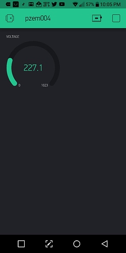
Connecting pzem004-t v3 with esp8266 and Blynk

Good day everyone,
Can someone please guide me how to setup my project? I followed the procedure described in PZEM-004T v3.0 and NodeMCU / Wemos Mini running on Blynk - How To procedure by creating new project, copied the codes as in first step.

void setup(){
  Serial.begin(115200); Serial.println("Start serial"); pzem.begin(9600); Serial.println("Start PZEM serial");
node.begin(1, pzem);  Serial.println("Start PZEM"); // 1 = ID MODBUS

WiFi.mode(WIFI_STA);
#if defined(USE_LOCAL_SERVER)
  WiFi.begin(ssid, pass);
  Blynk.config(AUTH, server, port);
#else
  Blynk.begin(AUTH, ssid, pass);
#endif
  while (Blynk.connect() == false) {}
  ArduinoOTA.setHostname(OTA_HOSTNAME);
  ArduinoOTA.begin();

//  timerTask1 = timer.setInterval(1000, updateBlynk);

}

void updateBlynk() {
  Blynk.virtualWrite(vPIN_VOLTAGE,               U_PR);
  Blynk.virtualWrite(vPIN_CURRENT_USAGE,         I_PR);
  Blynk.virtualWrite(vPIN_ACTIVE_POWER,          P_PR);
  Blynk.virtualWrite(vPIN_ACTIVE_ENERGY,         PPR);
  Blynk.virtualWrite(vPIN_FREQUENCY,             PR_F);
  Blynk.virtualWrite(vPIN_POWER_FACTOR,          PR_PF);
  Blynk.virtualWrite(vPIN_OVER_POWER_ALARM,      PR_alarm);
}

void loop(){
Blynk.run();
//ArduinoOTA.handle();
//timer.run();

result = node.readInputRegisters(0x0000, 10);
  if (result == node.ku8MBSuccess)  {
U_PR      = (node.getResponseBuffer(0x00)/10.0f);
I_PR      = (node.getResponseBuffer(0x01)/1000.000f);
P_PR      = (node.getResponseBuffer(0x03)/10.0f);
PPR       = (node.getResponseBuffer(0x05)/1000.0f);
PR_F      = (node.getResponseBuffer(0x07)/10.0f);
P

Then followed the second step and copied the codes and saved them as settingsPZEM.h in same folder but it gives me error

Arduino: 1.8.9 (Windows 10), Board: "NodeMCU 1.0 (ESP-12E Module), 80 MHz, Flash, Legacy (new can return nullptr), All SSL ciphers (most compatible), 4MB (FS:2MB OTA:~1019KB), v2 Lower Memory, Disabled, None, Only Sketch, 115200"

PZEM:6:26: error: settingsPZEM.h: No such file or directory

 #include "settingsPZEM.h"

                          ^

compilation terminated.

exit status 1
settingsPZEM.h: No such file or directory

This report would have more information with
"Show verbose output during compilation"
option enabled in File -> Preferences

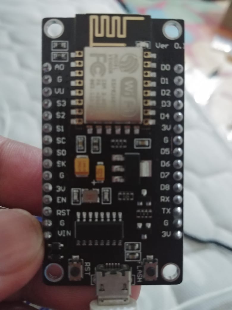
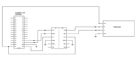
Tools I am using are Nodemcu ESP8266, PZEM004T V03 with level shifter as shown in the schematic. Also if someone can verify my connection between esp and pzem are ok as per the codes.
I know i am asking for too much but being beginner will help me a lot.
Thanks in advance
You’ve almost certainly named your settingsPZEM.h file incorrectly, or put it in the wrong location.

When you open the project in the Arduino IDE you should see two tabs, the main sketch and the settingsPZEM.h tab.

Pete.

1 Like

Thanks for your response.
Kindly see the snap and let me know if there is something wrong.

Looking at your screenshot, I think your settings file is actually called settingsPZEM.h.ino and windows is hiding the .ino extension on both files.

Change your folder view settings and in-check the “Hide extensions for known file types” option and you’ll see the problem.

Pete.

1 Like

issue is solved the moment I removed the extra extension, but unfortunately other issue arises.

sketch_nov16b:9:26: error: no matching function for call to 'SoftwareSerial::SoftwareSerial(const uint8_t&, const uint8_t&)'

 SoftwareSerial pzem(D5,D6);  // (RX,TX) connect to TX,RX of PZEM for NodeMC
no matching function for call to 'SoftwareSerial::SoftwareSerial(const uint8_t&, const uint8_t&)'

This report would have more information with
"Show verbose output during compilation"
option enabled in File -> Preferences.

Capture
Also this one

'pzem' was not declared in this scope

also this

'pzem' was not declared in this scope

Capture4

But strangely if i put // in the start, the error is not anymore.
Sorry if I ask for spoon feeding but your help means alot.

I’ve just tried it and the code from the thread that you linked compiled fine for me.

The code that you posted earlier wasn’t the complete code, as it missed all of the definitions section of the original code, but to get your first error message some of the definitions must have been in the sketch you were compiling.

I’d start by checking that you have all of the code from the original article (delete your code and re-paste it) and ensuring that all of the libraries are up to date (Sketch > Include Libraries > Manage Libraries).

Pete.

Hi Pete,
I have copied the exact same code as bellow, entered the wifi password , username, blynk key and local blynk IP details.

#include <ArduinoOTA.h>
#include <BlynkSimpleEsp8266.h>
#include <SimpleTimer.h>
#include <ModbusMaster.h>
#include <ESP8266WiFi.h>
#include "settingsPZEM.h"

#include <SoftwareSerial.h>  //  ( NODEMCU ESP8266 )
SoftwareSerial pzem(D5,D6);  // (RX,TX) connect to TX,RX of PZEM for NodeMCU
//SoftwareSerial pzem(D7,D8);  // (RX,TX) connect to TX,RX of PZEM
#include <ModbusMaster.h>
ModbusMaster node;
SimpleTimer timer;

//WiFi data
char ssid[] = "Put your WiFi SSID here";                    //WiFi Credential
char pass[] = "Put your WiFi password here";              //WiFi Password
char server[] = "Put your Blynk local server IP address here";         //Blynk local server IP address
int port = 8080;                        //Blynk local port
#define USE_LOCAL_SERVER                //Use local Blynk Server - comment-out if use Blynk hosted cloud service
#define AUTH    "put your Blynk App Authorization code here"    //PZEM-004v3 Auth code for Blynk Local Server

int timerTask1;
double U_PR, I_PR,  P_PR,  PPR, PR_F, PR_PF, PR_alarm;
uint8_t result;  uint16_t data[6];


void setup(){
  Serial.begin(115200); Serial.println("Start serial"); pzem.begin(9600); Serial.println("Start PZEM serial");
node.begin(1, pzem);  Serial.println("Start PZEM"); // 1 = ID MODBUS

WiFi.mode(WIFI_STA);
#if defined(USE_LOCAL_SERVER)
  WiFi.begin(ssid, pass);
  Blynk.config(AUTH, server, port);
#else
  Blynk.begin(AUTH, ssid, pass);
#endif
  while (Blynk.connect() == false) {}
  ArduinoOTA.setHostname(OTA_HOSTNAME);
  ArduinoOTA.begin();

//  timerTask1 = timer.setInterval(1000, updateBlynk);

}

void updateBlynk() {
  Blynk.virtualWrite(vPIN_VOLTAGE,               U_PR);
  Blynk.virtualWrite(vPIN_CURRENT_USAGE,         I_PR);
  Blynk.virtualWrite(vPIN_ACTIVE_POWER,          P_PR);
  Blynk.virtualWrite(vPIN_ACTIVE_ENERGY,         PPR);
  Blynk.virtualWrite(vPIN_FREQUENCY,             PR_F);
  Blynk.virtualWrite(vPIN_POWER_FACTOR,          PR_PF);
  Blynk.virtualWrite(vPIN_OVER_POWER_ALARM,      PR_alarm);
}

void loop(){
Blynk.run();
//ArduinoOTA.handle();
//timer.run();

result = node.readInputRegisters(0x0000, 10);
  if (result == node.ku8MBSuccess)  {
U_PR      = (node.getResponseBuffer(0x00)/10.0f);
I_PR      = (node.getResponseBuffer(0x01)/1000.000f);
P_PR      = (node.getResponseBuffer(0x03)/10.0f);
PPR       = (node.getResponseBuffer(0x05)/1000.0f);
PR_F      = (node.getResponseBuffer(0x07)/10.0f);
PR_PF     = (node.getResponseBuffer(0x08)/100.0f);
PR_alarm  = (node.getResponseBuffer(0x09));  
 } 

    Serial.print("U_PR:     "); Serial.println(U_PR);   // V
    Serial.print("I_PR:     "); Serial.println(I_PR,3);   //  A
    Serial.print("P_PR:     "); Serial.println(P_PR);   //  W 
    Serial.print("PPR:      "); Serial.println(PPR,3);   // kWh
    Serial.print("PR_F:     "); Serial.println(PR_F);    // Hz
    Serial.print("PR_PF:    "); Serial.println(PR_PF);  
    Serial.print("PR_alarm: "); Serial.println(PR_alarm,0);
Serial.println("====================================================");

updateBlynk();
  delay(1000);
}

kindly tell me what else I have to change to avoid these problems

Arduino: 1.8.9 (Windows 10), Board: "NodeMCU 1.0 (ESP-12E Module), 80 MHz, Flash, Legacy (new can return nullptr), All SSL ciphers (most compatible), 4MB (FS:2MB OTA:~1019KB), v2 Lower Memory, Disabled, None, Only Sketch, 115200"

Blynk-PZEM-004T-v3.0:34:27: error: no matching function for call to 'SoftwareSerial::SoftwareSerial(const uint8_t&, const uint8_t&)'

 SoftwareSerial pzem(D5, D6); // (RX,TX) connect to TX,RX of PZEM for NodeMCU  

                           ^

C:\Users\chatt\OneDrive\Documents\Arduino\Blynk-PZEM-004T-v3.0-master\Blynk-PZEM-004T-v3.0\Blynk-PZEM-004T-v3.0.ino:34:27: note: candidate is:

In file included from C:\Users\chatt\OneDrive\Documents\Arduino\Blynk-PZEM-004T-v3.0-master\Blynk-PZEM-004T-v3.0\Blynk-PZEM-004T-v3.0.ino:33:0:

C:\Users\chatt\AppData\Local\Arduino15\packages\esp8266\hardware\esp8266\2.6.0\libraries\SoftwareSerial\src/SoftwareSerial.h:49:5: note: SoftwareSerial::SoftwareSerial()

     SoftwareSerial();

     ^

C:\Users\chatt\AppData\Local\Arduino15\packages\esp8266\hardware\esp8266\2.6.0\libraries\SoftwareSerial\src/SoftwareSerial.h:49:5: note:   candidate expects 0 arguments, 2 provided

exit status 1
no matching function for call to 'SoftwareSerial::SoftwareSerial(const uint8_t&, const uint8_t&)'

This report would have more information with
"Show verbose output during compilation"
option enabled in File -> Preferences.

Other Issue as below


Arduino: 1.8.9 (Windows 10), Board: "NodeMCU 1.0 (ESP-12E Module), 80 MHz, Flash, Legacy (new can return nullptr), All SSL ciphers (most compatible), 4MB (FS:2MB OTA:~1019KB), v2 Lower Memory, Disabled, None, Only Sketch, 115200"

C:\Users\chatt\OneDrive\Documents\Arduino\Blynk-PZEM-004T-v3.0-master\Blynk-PZEM-004T-v3.0\Blynk-PZEM-004T-v3.0.ino: In function 'void setup()':

Blynk-PZEM-004T-v3.0:49:3: error: 'pzem' was not declared in this scope

   pzem.begin(9600);

   ^

exit status 1
'pzem' was not declared in this scope

This report would have more information with
"Show verbose output during compilation"
option enabled in File -> Preferences.

I have connected RX of PZEM to TX of ESP8266 nodemcu V3 and TX to the RX pin.

Regards.

I’m using version 2.4.2 of the Arduino core, as anything after that has too many bugs for my liking.
What happens if you downgrade to that version?

Did you check that your libraries are up to date?

Pete.

You have to update SoftwareSerial to latest version v6.1.1 by going to
Tools->Manage Libraries then select EspSoftwareSerial

same issue after updating the software serial library

1Capture4

if I put // before then the issue is gone, but iam not sure it will work this way

So the previous issue gone.
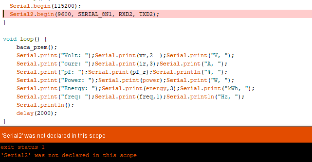
There is no Serial2 in the original code as well as your posted code.
If you add it, you have to declare it. We have no way to know if you don’t post the whole code.

Hi Khoih,
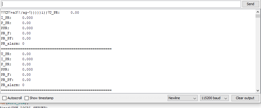
Thanks for help, the sketch uploads without any issue now, but the serial monitor shows the following data:


My setup schematic is at the top of the post.
i have modified only these 4 in the sketch:

//WiFi data
char ssid[] = "Put your WiFi SSID here";                    //WiFi Credential
char pass[] = "Put your WiFi password here";              //WiFi Password
char server[] = "Put your Blynk local server IP address here";         //Blynk local server IP address
int port = 8080;                        //Blynk local port
#define USE_LOCAL_SERVER                //Use local Blynk Server - comment-out if use Blynk hosted cloud service
#define AUTH    "put your Blynk App Authorization code here"    //PZEM-004v3 Auth code for Blynk Local Server

In blynk I have created second projecct with PZEM004T( first was for DHT22 sensor), but the app continuously shows PZEM disconnected and connects again,using the new generated key for this code.
For blink local server IP i have pinged blynk-cloud.com.
please let me know if some modification is required, I know i am close now to achieve this.

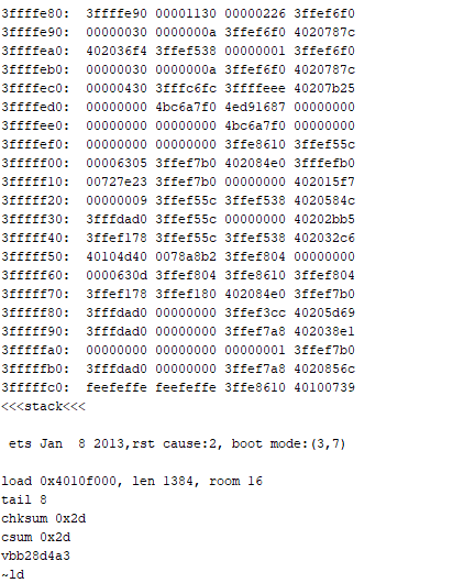
The code uploads now, can you please look into the following new issue

The stack dump that you’re seeing in your serial monitor is because the board is resetting.

I’m confused by a few things…

  1. are you using the SoftwareSerial port on D5/D6 to communicate with the PZEM, or the hardware serial port? If the latter then you can’t use this port for debugging as well.

  2. are you using your own local Blynk server, or the Blynk cloud servers?

Pete.

I am not sure, I have connected RX to the RX on the board coming from LV RX of the level shifter and TX to the TX on the board coming from LV side of the level shifter.
I believe it is Blynk cloud server.

Firstly, you alway connect Rx to Tx and vice versa.
Assuming that this is the code that you’re using:

then D5 is your software UART Rx pin, which connects to the PZEM Tx pin, and D6 is your software UART Tx pin which connects to the PZEM Rx pin (as is says in the comments).

You would certainly know if you’d built your own local server, and as you haven’t then you will be using the Blynk cloud servers. As a result, this line:

needs to be commented-out.

Pete.

Just a quick question, while using DHT22 I had to feed the blynk auth key only but here it needs to be connected to the cloud server, why it is required?
I commented out as you instructed but the issue is still there
sorry but google isnt of help or may be this thing is badly on my nerves.

With the DHT code you would have had to provide your Wi-FI SSID, Wi-Fi password and Blynk Auth code.
It would then have a line that says:

  Blynk.begin(AUTH, ssid, pass);

which connects the device to the Blynk cloud server.

This code is exactly the same, when not using the local server option, but has options that make it simpler to use a local server.

Did you make the wiring changes too?

Pete.

If you use the blocking Blynk.begin() in your setup() function and the board can’t connect to WiFi / Blynk server, the loop() function will never be executed. Therefore, anything you put there forever won’t run.
There have many discussions about this, you’d better do some more research on this blocking Blynk.begin() and non blocking Blynk.config() + Blynk.connect().

The following code, modified from original code, will show you how to use those functions, and will possibly fix your problems. It also cleans up the loop() and automatically connects / reconnects WiFi and Blynk whenever necessary, in setup() as well as in runtime loop().

#define USE_BLYNK_WM      0       // https://github.com/khoih-prog/Blynk_WM

#include <ArduinoOTA.h>

#if USE_BLYNK_WM
#include <BlynkSimpleEsp8266_WM.h>
#else
#include <BlynkSimpleEsp8266.h>
#endif

//#include <SimpleTimer.h>
#include <ModbusMaster.h>
#include <ESP8266WiFi.h>
#include "settingsPZEM.h"

#include <SoftwareSerial.h>  //  ( NODEMCU ESP8266 )
SoftwareSerial pzem(D5,D6);  // (RX,TX) connect to TX,RX of PZEM for NodeMCU
//SoftwareSerial pzem(D7,D8);  // (RX,TX) connect to TX,RX of PZEM
#include <ModbusMaster.h>
ModbusMaster node;
SimpleTimer timer;

#if !USE_BLYNK_WM
//WiFi data
char ssid[] = "****";          //WiFi Credential
char pass[] = "****";          //WiFi Password
char server[] = "****";        //Blynk local server IP address
int port = 8080;               //Blynk local port

#define AUTH    "****"    //PZEM-004v3 Auth code for Blynk Local Server
#endif

int timerTask1;
double U_PR, I_PR,  P_PR,  PPR, PR_F, PR_PF, PR_alarm;
uint8_t result;  uint16_t data[6];

#define UPDATE_INTERVAL_MS      5000

// Use 0 or 1 when you don't need to debug with many messages
#define DEBUG_LOOP              2

#define MODBUS_ID               1

void updateBlynk() 
{
  getPZEM();
 
  Blynk.virtualWrite(vPIN_VOLTAGE,               U_PR);
  Blynk.virtualWrite(vPIN_CURRENT_USAGE,         I_PR);
  Blynk.virtualWrite(vPIN_ACTIVE_POWER,          P_PR);
  Blynk.virtualWrite(vPIN_ACTIVE_ENERGY,         PPR);
  Blynk.virtualWrite(vPIN_FREQUENCY,             PR_F);
  Blynk.virtualWrite(vPIN_POWER_FACTOR,          PR_PF);
  Blynk.virtualWrite(vPIN_OVER_POWER_ALARM,      PR_alarm);
}

uint8_t getPZEM()
{
  result = node.readInputRegisters(0x0000, 10);
  
  if (result == node.ku8MBSuccess)  
  {
    U_PR      = (node.getResponseBuffer(0x00)/10.0f);
    I_PR      = (node.getResponseBuffer(0x01)/1000.000f);
    P_PR      = (node.getResponseBuffer(0x03)/10.0f);
    PPR       = (node.getResponseBuffer(0x05)/1000.0f);
    PR_F      = (node.getResponseBuffer(0x07)/10.0f);
    PR_PF     = (node.getResponseBuffer(0x08)/100.0f);
    PR_alarm  = (node.getResponseBuffer(0x09));

    #if (DEBUG_LOOP > 0)
    Serial.print("U_PR:     "); Serial.println(U_PR);   // V
    Serial.print("I_PR:     "); Serial.println(I_PR,3); //  A
    Serial.print("P_PR:     "); Serial.println(P_PR);   //  W 
    Serial.print("PPR:      "); Serial.println(PPR,3);  // kWh
    Serial.print("PR_F:     "); Serial.println(PR_F);   // Hz
    Serial.print("PR_PF:    "); Serial.println(PR_PF);  
    Serial.print("PR_alarm: "); Serial.println(PR_alarm,0);
    Serial.println("====================================================");
    #endif   
  }
  #if (DEBUG_LOOP > 0)
  else
    Serial.println("PZEM: can't get data");
  #endif
  
  return result;
}

// Use this to avoid being blocked here if no WiFi
void connectWiFi(const char* ssid, const char* pass)
{
    #if (DEBUG_LOOP > 0)
    Serial.println("Connecting to " + String(ssid));
    #endif
    
    WiFi.mode(WIFI_STA);
    if (pass && strlen(pass)) 
    {
        WiFi.begin(ssid, pass);
    } else 
    {
        WiFi.begin(ssid);
    }
    int i = 0;
    while ((i++ < 30) && (WiFi.status() != WL_CONNECTED)) 
    {
        BlynkDelay(500);
    }

    #if (DEBUG_LOOP > 0)
    if (WiFi.status() == WL_CONNECTED)
      Serial.println("Connected to " + String(ssid));
    else
      Serial.println("Can't connect to " + String(ssid));
    #endif
}

void connectWiFiAndBlynk()
{
  if (WiFi.status() != WL_CONNECTED)
  {
    connectWiFi(ssid, pass);  
  }
  else
  {
    #if (DEBUG_LOOP > 0)
    Serial.println("Trying connecting to BlynkServer " + String(server));
    #endif
    Blynk.connect();

    if (Blynk.connected())
    {
      #if (DEBUG_LOOP > 0)
      Serial.println("Connected to BlynkServer " + String(server));
      #endif
    }     
  }
}

void setup()
{
  Serial.begin(115200); 
  Serial.println("\nStart serial"); 
  pzem.begin(9600); 
  Serial.println("Start PZEM serial");
  node.begin(MODBUS_ID, pzem);  
  Serial.println("Start PZEM"); // 1 = ID MODBUS

  #if USE_BLYNK_WM
    Blynk.begin();
  #else
    // Use this to avoid being blocked here if no WiFi
    //connectWiFi(ssid, pass);
    Blynk.config(AUTH, server, port);

    connectWiFiAndBlynk();
    //Blynk.connect();
  #endif  
    
  ArduinoOTA.setHostname(OTA_HOSTNAME);
  ArduinoOTA.begin();
  timerTask1 = timer.setInterval(UPDATE_INTERVAL_MS, updateBlynk);
}

void loop()
{
  if (Blynk.connected())
  {
    Blynk.run();
  }
  else
  {
    connectWiFiAndBlynk();
  }
  
  ArduinoOTA.handle();
  timer.run();  
}

As a last resort I unplugged the level shifter and connected the Pzem with board directly with 5V to VV of ESP and ground to G ,RX & TX with D5 and D6 of ESP, applied your code and guess what, my dream come true finally.


A sign of relief for me at the moment but iam afraid this way the board wouldn’t get fried.