I saw this post from @Vitokhv recently and decided to order one of these boards and have a play around with it.
Here’s a link to another supplier on AliExpress who’s selling the same board:
The boards are basically an ESP8266 with two 74HC595 shift registers that allow the 16 onboard relays to be controlled via just 4 GPIOs.
They seem to be available in versions that work with a 5v, 12v or 24v supply voltage, and the relays are supposed to be capable of switching up to 250v at 10A each. I went for the version that requires a 12v power supply, as this gave the most versatility for me, as I may use it as part of my 12v solar power system.
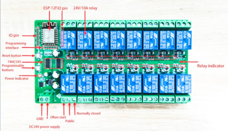
The board doesn’t have a USB port, so you’ll need an FTDI adapter, some jumper wires and soldering iron to be able to program it, and a suitable power supply (5v, 12v or 24v DC, depending on which version you’ve chosen).
I’ve not found any retailers that provide a link to example sketches for these boards, and I’ve not found any GitHub examples either. That meant I had to get my multimeter out and start reverse-engineering the wiring, then piece together some test code to get the board working.
Below is the info I worked-out on the wiring of the board, you skip this if you want to get straight into the example. It’s simply provided for anyone who wants to do other things with these boards.
Onboard Wiring
The onboard ESP8266 is connected to the 74HC595 shift registers as follows:
| ESP8266 Pins | 74HC595 Connections |
|---|---|
| GPIO 14 | Serial Input (DS) - Pin 14 on 74HC595 No 1 |
| GPIO 12 | Shift Register Clock (RCLK or ST_CP) - Pin 12 |
| GPIO 13 | Storage Register Clock (SRCLK or SH_CP) - Pin 11 |
| GPIO 5 | Output Enable (OE) - Pin 13 |
The Output Enable pin is normally pulled LOW when using 74HC595s, but on this board it is connected to GPIO 5 of the ESP9266, so this needs to be pulled LOW for the outputs to work.
Getting ready to program the board
As I said earlier, you need an FTDI programmer, as the board doesn’t have a USB port or TTL to USB chip on-board.
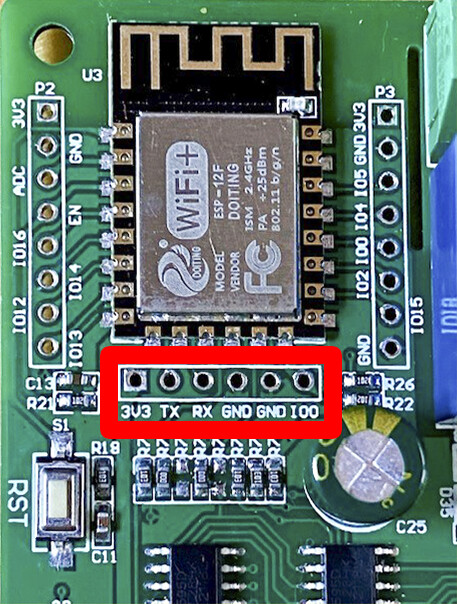
You need to start by soldering a 6-pin header onto the “Programming Interface” pins highlighted in red below…
Below is the board with the FTDI adapter connected…
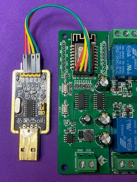
Note that the Rx pin on the board needs to be connected to the Tx pin on the FTDI and vice-versa.
Also, ensure that the FTDI is set to work at 3.3v logic levels.
To put the board into programming mode, pin GPIO 0 must be shorted to GND as the board is powered-up. This can be achieved by shorting-out the remaining two pins of the programming interface (labelled GND and IO0) with one of the supplied jumpers, or by pressing and holding the on-board button labelled “KEY” whilst powering-up the board (it can be released as soon as this is done).
At this stage the power can be provided by the FTDI adapter, so it shouldn’t be necessary to connect anything to the supply terminals labelled “GND” and “VIN”.
You can then identify the COM port that relates to the FTDI adapter and upload code as normal. In the Arduino IDE, you can choose any of the NodeMCU variants as the board type.
Note that after the upload has completed, and you see the “Hard resetting via RTS pin…” message in the IDE, you need to follow this by pressing the other onboard button (labelled “RST”) . If you placed a jumper across the GND & IO0 pins then this needs to be removed before performing the reset.
When the board is being powered only by the FTDI adapter the LED indicators for each relay will light-up when the relay is energised, but you won’t hear the relay contacts click, as there isn’t enough current available from the FTDI to actuate the relays.
Creating the Blynk Template and Datastreams
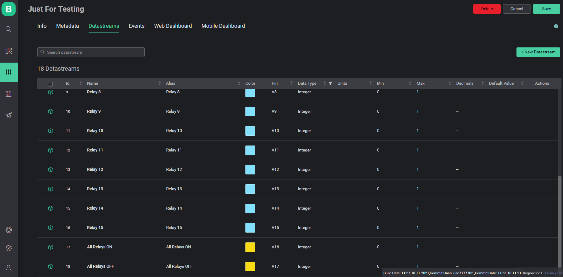
To use the example code below, you will need to create a template in the Blynk web dashboard and add 18 virtual datastreams using virtual pins 0-17 inclusive.
All datastreams are virtual, and have a data type of Integer with a Min value of 0 and a Max value of 1.
I gave the datastreams attached to virtual pins 0-15 the name “Relay 0” to “Relay 15”
The datastream attached to virtual pin 16 is called “All Relays ON” and the one attached to pin V17 is called “All Relays OFF”.
The names you use don’t really matter, but it is important to use the virtual pin numbers I’ve specified above.
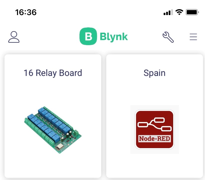
If you want to add a picture of the device to your template then you can. Once you’ve added your device(that bit comes later) then you’ll see the picture on the tile for that device, like this…
The Blynk Sketch
I’ve tried to keep things as simple as possible, but at the same time making the code flexible enough for you to tailor to your own needs.
I’ve based the sketch on the Blynk Edgent ESP8266 example, and you need to open this example (File > Examples > Blynk > Blynk.Edgent > Edgent_ESP8266) in the Arduino IDE.
You then need to replace the contents of the Edgent_ESP8266 tab with the code below.
Trying to run this code without the rest of the Edgent example will not work.
You’ll need to copy and paste your BLYNK_TEMPLATE_ID and BLYNK_DEVICE_NAME from the template you created into the sketch (lines 2 and 3 of the sketch).
// Fill-in information from your Blynk Template here
#define BLYNK_TEMPLATE_ID "Your Template ID"
#define BLYNK_DEVICE_NAME "Your Device ID"

#define BLYNK_FIRMWARE_VERSION        "0.1.0"

#define BLYNK_PRINT Serial
//#define BLYNK_DEBUG

#define APP_DEBUG
#define USE_NODE_MCU_BOARD

#include "BlynkEdgent.h"

// Variables for 74HC595 code
#define SER_Pin 14 // Serial Input pin on 74HC595 No 1 (74HC595 Pin 14). Otherwise known as DS
#define RCLK_Pin 12 // Shift Register Clock Pin on both 74HC595s (74HC595 Pin 12). Otherwise known as ST_CP
#define SRCLK_Pin 13 // Storage Register Clock Pin on both 74HC595s (74HC595 Pin 11). Otherwise known as SH_CP
#define outout_enablePin 5  // Output Enable pin on both 74HC595s (74HC595 Pin 13). Must be pulled LOW to enable the outputs

boolean registers[16]; // Zero-indexed array (0-15) which holds the state of the 16 relays

boolean just_restarted = true;  // flag to aoid turning all relays off at startup

void setup()
{
  Serial.begin(74880);
  pinMode(SER_Pin, OUTPUT);
  pinMode(RCLK_Pin, OUTPUT);
  pinMode(SRCLK_Pin, OUTPUT);
  pinMode(outout_enablePin, OUTPUT);
  digitalWrite(outout_enablePin,LOW);

  BlynkEdgent.begin();
}

void loop()
{
  BlynkEdgent.run();
}


BLYNK_CONNECTED()
{
  for(int loop = 0; loop <=  15; loop++)
  {
    Blynk.syncVirtual(loop);
  }
  just_restarted = false;
  writeRegisters();
}

BLYNK_WRITE_DEFAULT()
{
  int widget_pin = request.pin;      // Which virtual pin triggered this BLYNK_WRITE_DEFAULT callback?
  int widget_value = param.asInt();  // Get the value from the virtual pin (O = off, 1 = on)

  setRegisterPin(widget_pin, widget_value); // Set the correct register to the correct value (HIGH/LOW for on/off)
  if(!just_restarted)
  {
    writeRegisters();               // Write the stored register values out to the controller
  }
}


BLYNK_WRITE(V16) // Button labelled All ON
{
  if(param.asInt())
  {
    for(int loop = 0; loop <=  15; loop++)
    {
     registers[loop] = HIGH;
     Blynk.virtualWrite(loop,1);
    }
  writeRegisters();                         // Write the stored register values out to the controller
  }
}

BLYNK_WRITE(V17) // Button labelled All OFF
{
  if(param.asInt())
  {
    for(int loop = 0; loop <=  15; loop++)
    {
     registers[loop] = LOW;
     Blynk.virtualWrite(loop,0);
    }
  writeRegisters();                         // Write the stored register values out to the controller
  }
}


void clearRegisters() // Clear registers variables
{
  for(int i = 15; i >=  0; i--)
  {
   registers[i] = LOW;;
  }
}

void writeRegisters() // Write the contents of the registers array out to the relays
{
  digitalWrite(RCLK_Pin, LOW);
  for(int i = 15; i >=  0; i--)
  {
    digitalWrite(SRCLK_Pin, LOW);
    int val = registers[i];
    digitalWrite(SER_Pin, val);
    digitalWrite(SRCLK_Pin, HIGH);
  }
    digitalWrite(RCLK_Pin, HIGH);
}

void setRegisterPin(int index,int value) //Set register variable to HIGH or LOW
{
  if (index >=0 && index <=15)
  {
    if (value ==0 || value ==1)
    {
      registers[index] = value; // we make it here if the index is 1-15 and thge value is 0 or 1
    }
    else
    {
      Serial.println("value must be either 0 or 1");
    }
  }
  else
  {
    Serial.println("index must be between 0 and 15");
  }
}
Put the board into programming mode as described above, then upload the sketch and reset the board afterwards (don’t forget to remove the GPIO0 jumper first).
You can then go through the provisioning process in the app (add device…) then add the required widgets to the app as described below…
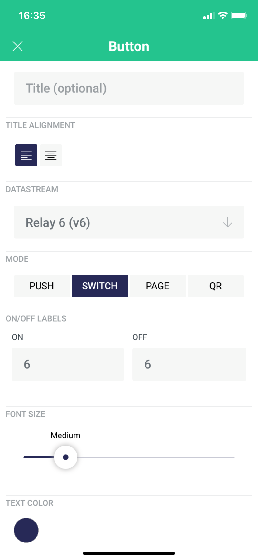
In the app, add one button, set to SWITCH mode for relays 0-15 like this:
I set the buttons up with an ON and OFF labels to be the same as the number of the relay they will be controlling, like this:
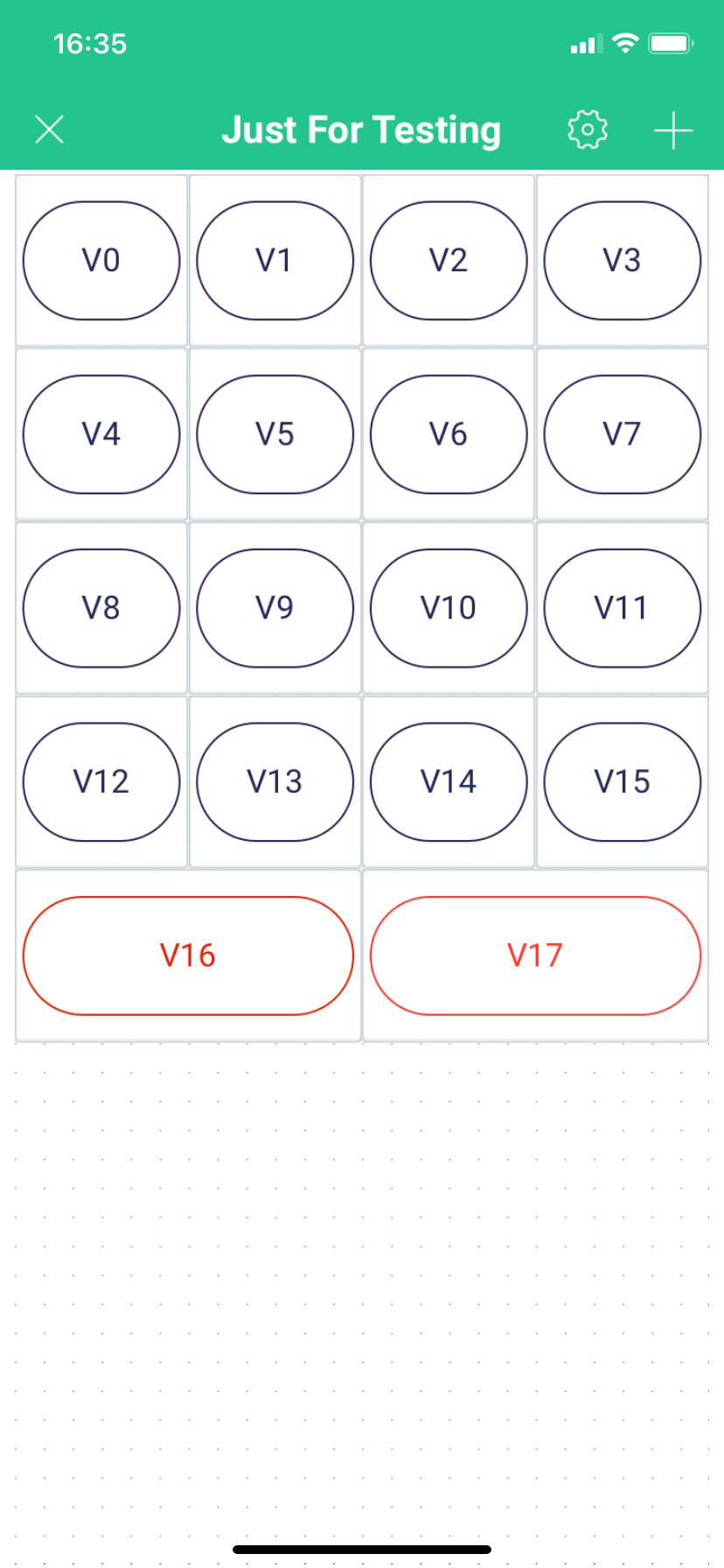
Buttons 16 and 17 are set to PUSH mode and the On and OFF labels are set to “ALL ON” for V16 and “ALL OFF” for V17. When you exit edit mode the app should look like this:

If you’ve done everything correctly then the buttons should control the relays, and the ALL ON and ALL OFF buttons should do what you’d expect them to.
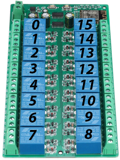
The relays on the board are numbered like this:
As I said earlier, the FTDI adapter should provide enough power to light the LEDs that correspond to each relay, not not actuate the relays.
Now is a good time to disconnect the FTDI adapter and power the board with a proper PSU of the correct voltage. Future software updates can be applied OTA using Blynk.Air.
When you’re using Blynk.Air, don’t forget to increment this line:
#define BLYNK_FIRMWARE_VERSION "0.1.0"
before exporting the compiled binary.
Obviously, if you want to do any debugging then you’ll need the FTDI to view the serial output from the board.
![]() It’s probably also a good time to remind you that mains voltages can be lethal, so take care when you start wiring-up the supply and the load connections for the relays!
It’s probably also a good time to remind you that mains voltages can be lethal, so take care when you start wiring-up the supply and the load connections for the relays! ![]()
How the sketch works
I’ve used the BLYNK_WRITE_DEFAULT() callback to keep the code compact. This saves using 16 BLYNK_WRITE(vPin) callbacks, one for each of the 16 switch widgets. The “ALL ON” and “ALL OFF” switches have their own BLYNK_REITE callbacks as they perform different functions.
The registers array is a place to store the current state of each relay. When any relay on the board is updated, you have to tell the board the state of all 16 relays, so this array is crucial, as a place to store these values.
The setRegisterPin() function is used to update the specified entry in the registers array and the writeRegisters() function outputs each of the stored values in he registers array to the board.
When the board is rebooted, the 74HC595 controllers remember their previous state, and the relays that were on previously are turned back on.
The BLYNK_CONNECTED() function then synchronises the relays with the app, so if the app was used to change the state of any of the relays while the board was off then the relay states will be changed to reflect the app.
This is where I discovered a minor problem when testing the sketch. Because the registers array is initialised with all values set to 0 when the board restarts, the first Blynk.syncVirtual(loop) command would set relay 0 to the same state as the app, but turn all of the other relays off (because the array holds a zero for relays 1-15).
I’ve resolved this by introducing the just_restarted flag ensure that the array values aren’t written to the 74HC595 registers until all of the Blynk.syncVirtual comamnds have completed, and all elements of the registers array are populated with the correct values.
If you’d prefer to have all of the relays turned off at start-up then simply add writeRegisters(); to void setup just before BlynkEdgent.begin();
Why are the relays numbered 0-15 ?
Because an array is used to hold the current state for each relay, and C++ arrays are always zero-indexed, I’ve gone for the easy option of using numbers 0-15 for the relays, and using virtual pins 0-15 to represent each relay. This allows the widget pin number from the BLYNK_WRITE_DEFAULT() callback to be passed directly to the setRegisterPin function.
If you wanted to translate the array numbers 0-15 into something different then you could, but in reality I think you’d use labels for the widgets that relate to the wiring circuit or appliance that’s being switched, and allow the 0-15 numbering to be used in the background
The setRegisterPin function has error checking in palace to prevent numbers outside of the 0-15 range to be used, and also to reject values other than 0 (for Off) and 1 (for On).
Can I use the unused GPIOs for other things ?
You could solder the other headers onto the board and use the unused GPIOs for sensors etc, if you wanted to make a self-contained board that switches some of the outputs on/off in certain circumstances.
Here’s a table of the pins, and their availability for sensors etc…
| ESP8266 Pins | Comments |
|---|---|
| GPIO 0 | Connected to the KEY button - Used to reset the Edgent Provisioning |
| GPIO 1 | Tx - Not recommended for use as a sensor pin |
| GPIO 2 | Onboard LED - Used by Edgent Provisioning |
| GPIO 3 | Rx - Not recommended for use as a sensor pin |
| GPIO 4 | Default SCL pin - Can be used |
| GPIO 5 | Used to control the Output Enable pin on the 74HC595 - Do not use |
| GPIO 6-11 | Internal pins - Unavailable for use |
| GPIO 12 | Shift Register Clock (RCLK or ST_CP) - Pin 12 - Do not use |
| GPIO 13 | Storage Register Clock (SRCLK or SH_CP) - Pin 11 - Do not use |
| GPIO 14 | Serial Input (DS) - Pin 14 on 74HC595 No 1 - Do not use |
| GPIO 15 | Must be LOW during boot - Use with extreme care |
| GPIO 16 | Normally used for sleep_wake - Use with care |
| ADC | Analog input - Can be used |
As you can see, there are a few pins that could be used for additional sensors, but not many.
Pete.
