Blynk Legacy is no longer supported, and will be retired in future.
But, if you want to take my sketch and convert it to Blynk Legacy (not a difficult task) then you’re welcome to do so.
sorry, I am deaf but i am basic wrote english. I dont know make add project adruino ino for timer
If you can make add timer rtc for arduino file ino.
i want send picture…
thank you and kind regards
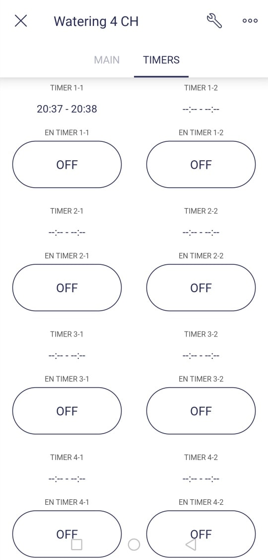
There isn’t much documentation for the IoT version of the time input widget, but there are plenty of examples for the Legacy version which works in the same way.
Take care not to confuse this with the Timer widget, which worked very differently in Legacy, but doesn’t exist in IoT because it has been replaced by Automations.
The Time Input widget requires a virtual datastream of the type String.
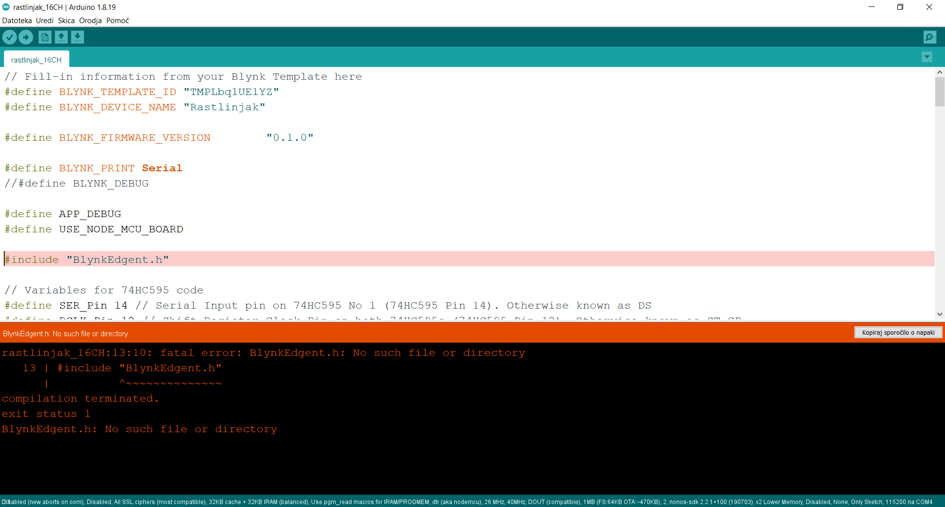
The sketch uses Blynk Edgent, which uses dynamic provisioning of WiFi credentials, as well as Auth tokens.
That’s why my tutorial says…
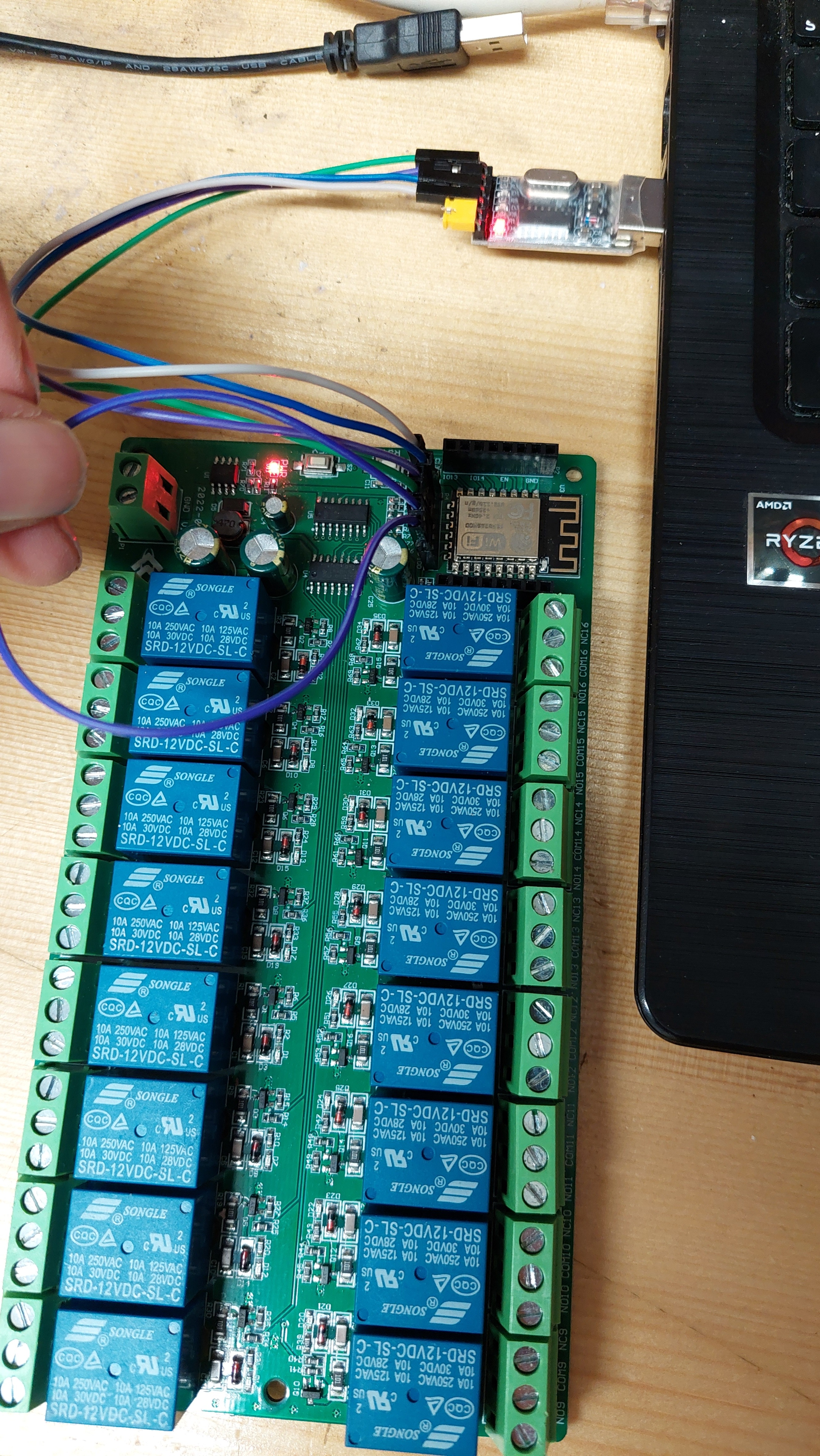
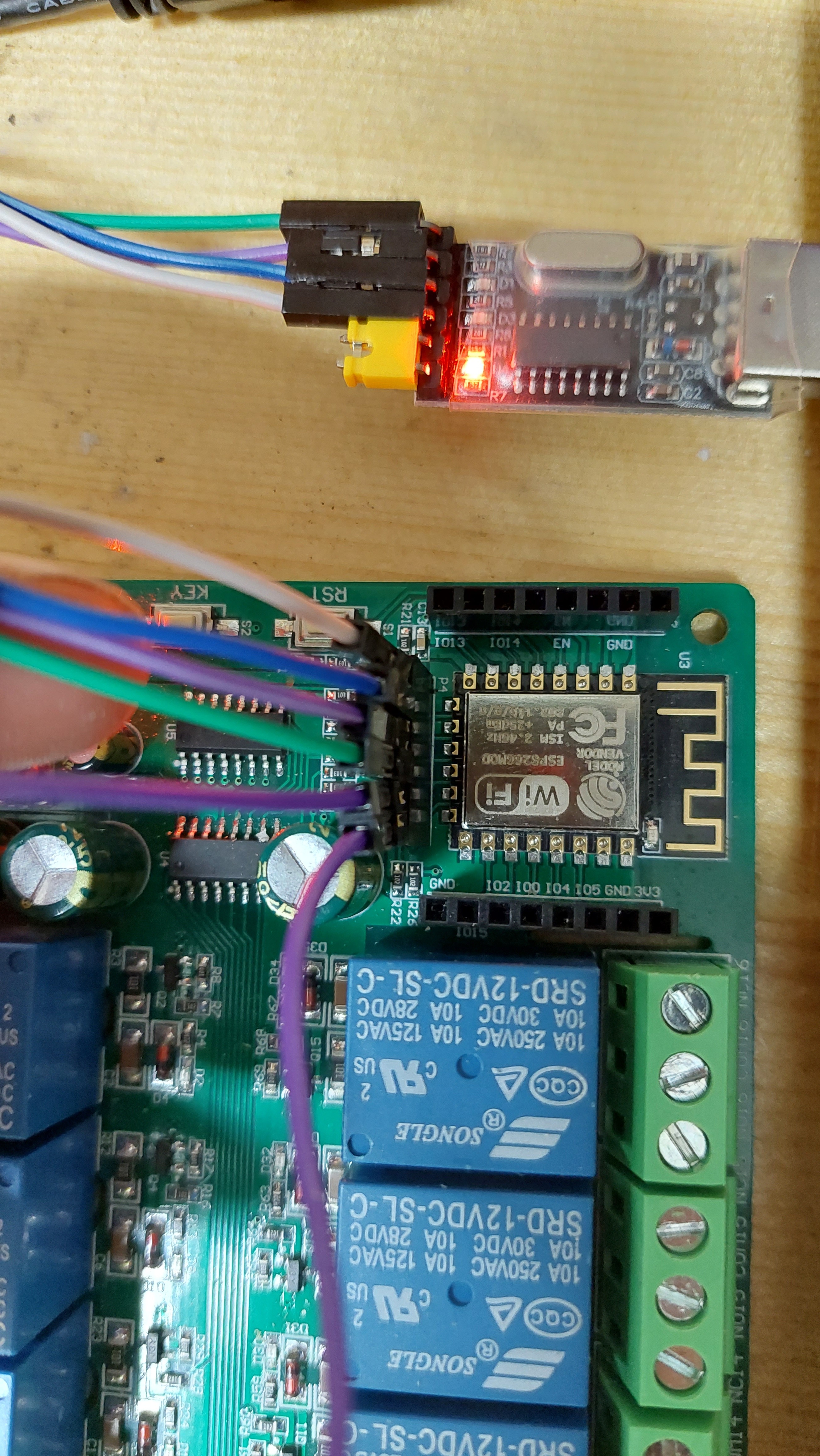
Put the board into programming mode as described above, then upload the sketch and reset the board afterwards (don’t forget to remove the GPIO0 jumper first). You can then go through the provisioning process in the app (add device…) then add the required widgets to the app as described below…
It really would help if you read the quite detailed instructions that I provided in my original post…
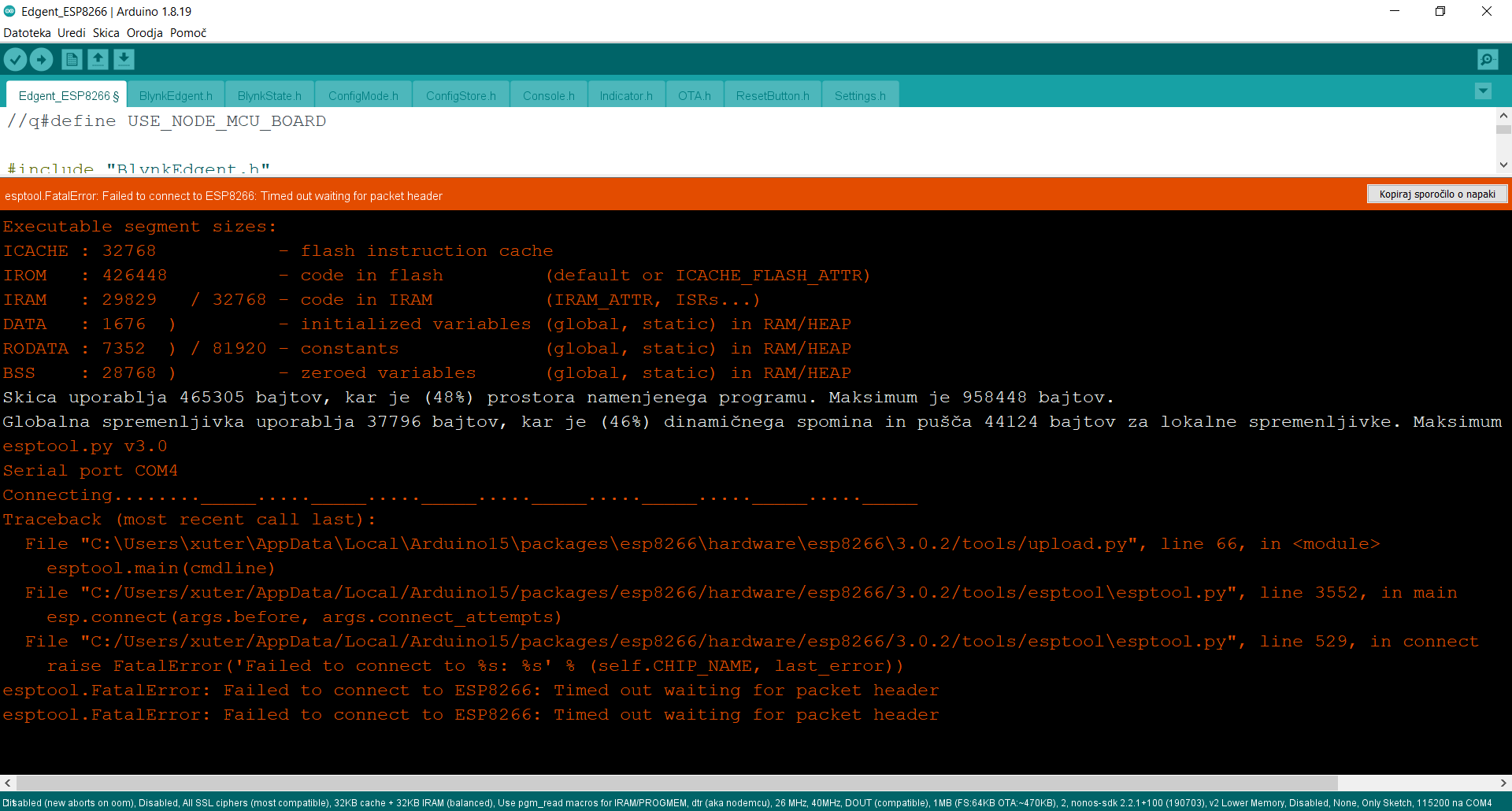
I’ve based the sketch on the Blynk Edgent ESP8266 example, and you need to open this example (File > Examples > Blynk > Blynk.Edgent > Edgent_ESP8266) in the Arduino IDE.
You then need to replace the contents of the Edgent_ESP8266 tab with the code below.
Trying to run this code without the rest of the Edgent example will not work.
I could quote the bit of the original post which describes how to put the board into programming mode, but I’ve already quoted sections from it twice because you can’t be bothered to read it properly.
The answer is in the original topic, seek and ye shall find.
cheers. I managed to make it work. i’m wrong usb connection. formerly tx - tx, rx - rx. fix now tx - rx, rx - tx. everything works … great. thank you again