I’m not convinced that you have the flame sensor running correctly yet. So I wouldn’t move on to adding extra sensors until the first one is running correctly.
I’ll be back to this code and remove the buzzer.
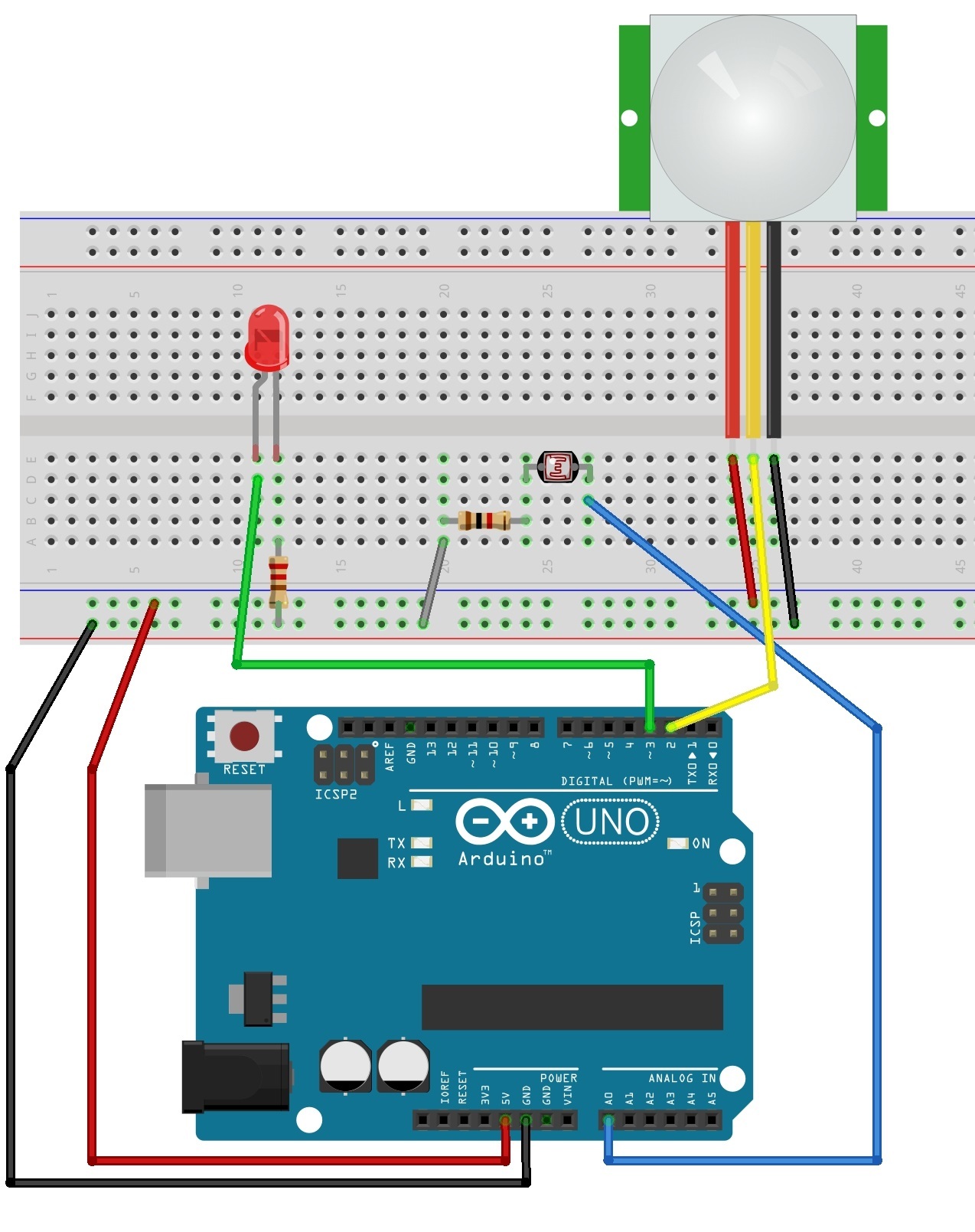
I want to add this circuit to my flame sensor circuit:
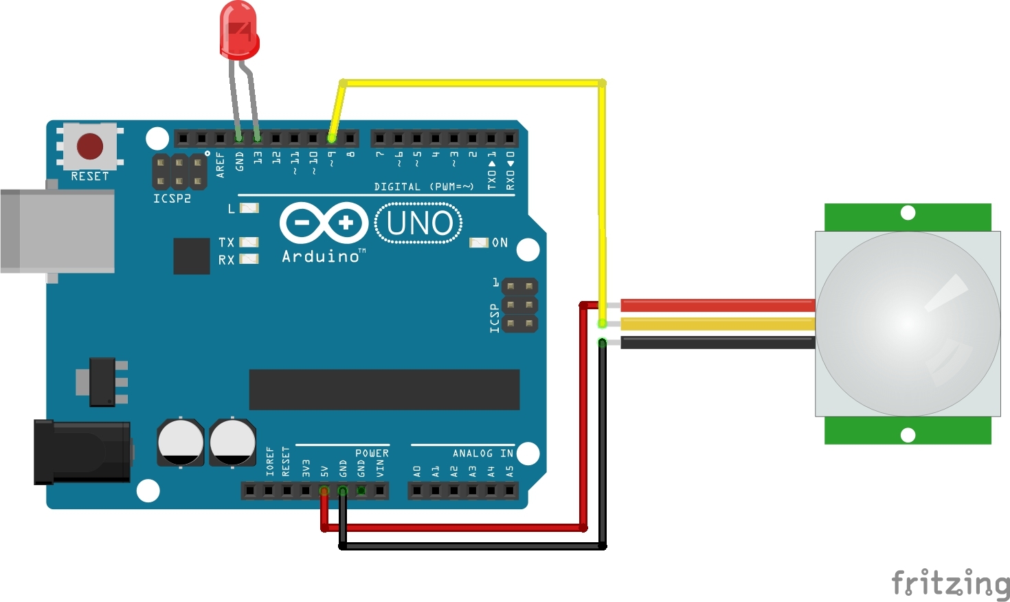
and this circuit:
Here is the code for first circuit:
#define LDR 0
#define PIR 2
#define LED 3

int pirState;
int ldrValue;
void setup() {
   pinMode(LED, OUTPUT);
   pinMode(PIR, INPUT);
   digitalWrite(LED, LOW);
}
void loop(){
ldrValue = analogRead(LDR);
   if (ldrValue <= 300) { // dark
      digitalWrite(LED, HIGH);
}
  else {
     pirState = digitalRead(PIR);
     if (pirState == HIGH) {
         digitalWrite(LED, HIGH);
         delay(1000);
         digitalWrite(LED, LOW);
         delay(1000);
       }
    else { // pirState == LOW
         digitalWrite(LED, LOW);
      }
    }
    // The processing in the Arduino occurs faster
    // than the response from the PIR, and adding this delay
    // eliminated a flickering on the LED
    delay(1000);
    }
And the this code for second circuit:
int ledPin = 13;
int pirPin = 9;
int val = 0;

void setup()
{
   pinMode (ledPin,OUTPUT);
   pinMode (pirPin, INPUT);
}
void loop ()
{
   val = digitalRead(pirPin);
   digitalWrite(ledPin,val);

   if (val == 1)
   digitalWrite(ledPin,LOW);
}
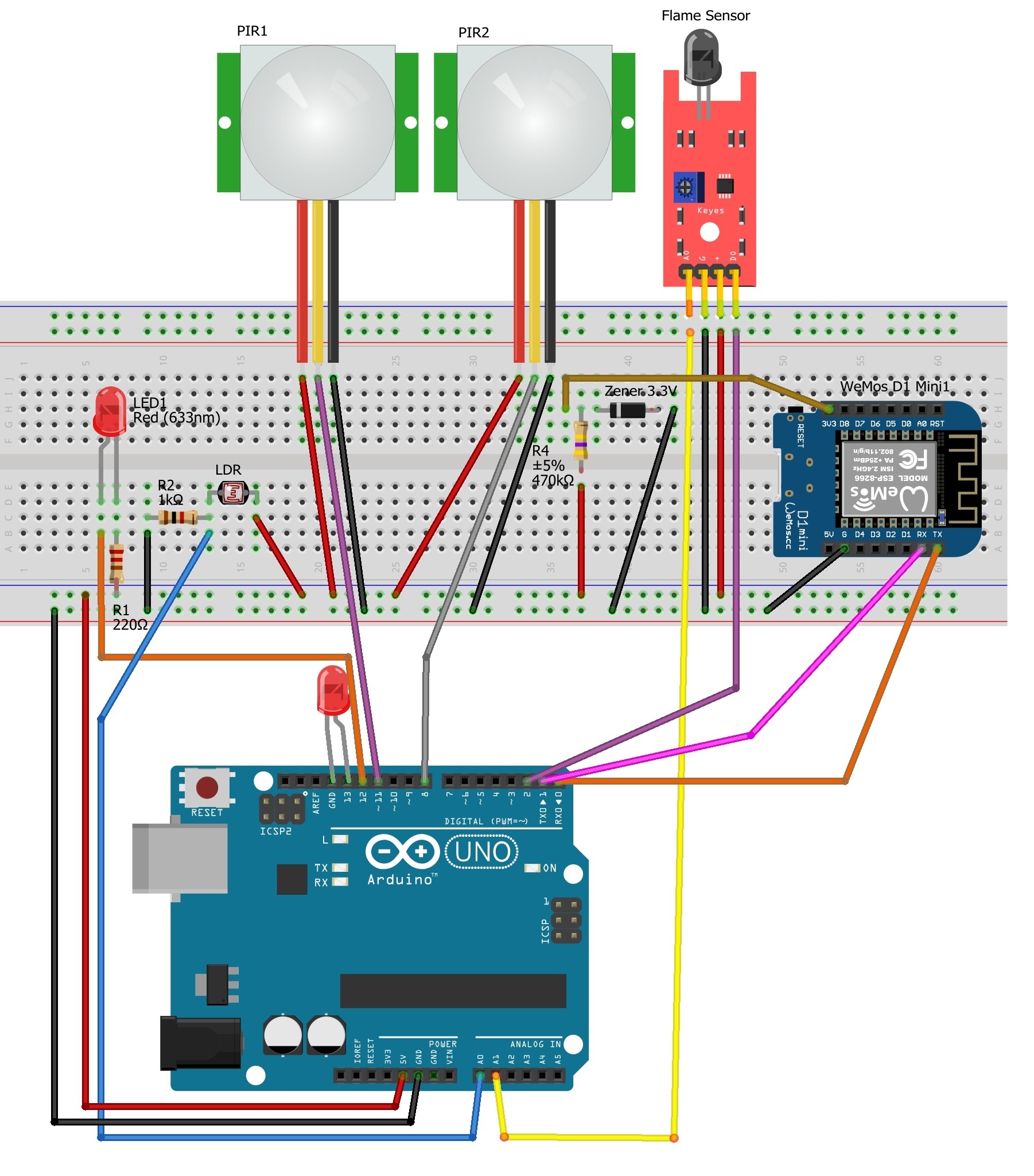
But, the problem is I need two analog pin, that is for LDR and flame sensor, whereas the wemos only have an analog pin. What should I do? Should I add a board again?
I have combine the circuit:
And the code:
#define BLYNK_PRINT Serial
#include <ESP8266WiFi.h>
#include <BlynkSimpleEsp8266.h>

#define LDR A0
#define PIR1 11
#define LED1 12
#define PIR2 8
#define LED2 13

// You should get Auth Token in the Blynk App.
// Go to the Project Settings (nut icon).
char auth[] = "******************************";

// Your WiFi credentials.
// Set password to "" for open networks.
char ssid[] = "Redmi 3s";
char pass[] = "*********";

int pirState1; // define numeric variables val for PIR1
int ldrValue;

int pirState2 = 0;// define numeric variables val for PIR2
//int buzzer = D1 ;// define buzzer Interface
int flame = 2; // define the flame sensor interface
int analoog = A1; // define the flame sensor interface

int val ;// define numeric variables val
float sensor; //read analoog value

BlynkTimer timer;

void readSensor1()
{
   ldrValue = analogRead(LDR);

   if (ldrValue <= 270) { // dark
   digitalWrite(LED1, HIGH);
}
   else {
   pirState1 = digitalRead(PIR1);
   if (pirState1 == HIGH) {
   digitalWrite(LED1, HIGH);
   delay(1000);
   digitalWrite(LED1, LOW);
   delay(1000);
}
   else { // pirState1 == LOW
   digitalWrite(LED1, LOW);
}
}

void readSensor2()
{
   pirState2 = digitalRead(PIR2);
   digitalWrite(LED2,pirState2);

   if (pirState2 == 1)
      digitalWrite(LED2,LOW);
 }

void readSensor3()
{
   sensor = analogRead(analoog);
   Serial.println(sensor);  // display temperature
   //long uptime = millis() / 60000L;

  // You can send any value at any time.
  // Please don't send more that 10 values per second.
  Blynk.virtualWrite(V1, millis() / 1000);

  val = digitalRead (flame) ;// digital interface will be assigned a value of 3 to read val
  if (val == HIGH) // When the flame sensor detects a signal, buzzer beep
  {
     //digitalWrite (buzzer, HIGH);
     Blynk.email("nurlela.dabukke@gmail.com", "Flame!!!", "Sensor activated");
  }
     //else
  //{
  // digitalWrite (buzzer, LOW);
   //}
  // Actually send the message.
   // Note:
   //   We allow 1 notification per 15 seconds for now.
   //Blynk.notify(String("Running for ") + uptime + " minutes.");
  }

 void setup()
 {
    pinMode(LED, OUTPUT);
    pinMode(PIR1, INPUT);
    digitalWrite(LED1, LOW);

    pinMode (LED2,OUTPUT);
    pinMode (PIR2, INPUT);

    //pinMode (buzzer, OUTPUT) ;// define buzzer as output interface
    pinMode (flame, INPUT) ;// output interface defines the flame sensor
    pinMode (analoog, INPUT) ;// output interface defines the flame sensor

    // Debug console
    Serial.begin(115200);

    Blynk.begin(auth, ssid, pass);
    // You can also specify server:
    //Blynk.begin(auth, ssid, pass, "blynk-cloud.com", 8442);
    //Blynk.begin(auth, ssid, pass, IPAddress(192,168,1,100), 8442);

    // Notify immediately on startup
    Blynk.notify("Device started");

    // Notify immediately on startup
    if(val==HIGH){
     //Blynk.notify("Flame!!!");
     //Blynk.email("nurlela.dabukke@gmail.com", "Flame!!!", "Sensor activated");
     // Setup a function to be called every minute
    timer.setInterval(10L, readSensor);
  }
  // Setup a function to be called every 200ms Costas
  timer.setInterval(150L, readSensor);  // Costas
  //Blynk.email("nurlela.dabukke@gmail.com", "Flame!!!", "Sensor activated");
 }

  void loop()
  {
      Blynk.run();
      timer.run();
  }
I want to combine Wemos to Arduino, but I still don’t know how to call the function if I have three functions. By the way, the LDR and both PIR don’t need connect to WiFi. Could you help me to fix it?
You are using the wrong connection method in your sketch.
Take a look at the ESP8266_Shield example but study closely the commented out lines because the sketch is written for a Mega / Leonardo that has more than one serial port. As you are using an Uno you will need to make some changes and just to warn you this connection method can be very difficult to set up.
Then, is it mean the one which connect to PC is wemos? How about setting board on arduino?
From your limited understanding it will be very, very difficult for you to setup the WeMos as a shield.
If I were you I would work more slowly through the WeMos only projects and then consider WeMos as a shield when you are more familiar with ESP’s and Blynk.
Sorry for my limited understanding cause it’s my first time to use Wemos as arduino’s shield. It’s my first time to use Arduino and WiFi board at the same time.
I have remake the sketch:
#define BLYNK_PRINT Serial
#include <ESP8266WiFi.h>
#include <BlynkSimpleEsp8266_SSL.h>

#define LDR A0
#define PIR1 11
#define LED1 12
#define PIR2 8
#define LED2 13

// You should get Auth Token in the Blynk App.
// Go to the Project Settings (nut icon).
char auth[] = "***********************************";

// Your WiFi credentials.
// Set password to "" for open networks.
char ssid[] = "Redmi3s";
char pass[] = "********";

int pirState1; // define numeric variables val for PIR1
int ldrValue;

int pirState2 = 0;// define numeric variables val for PIR2

//int buzzer = D1 ;// define buzzer Interface
int flame = 2; // define the flame sensor interface
int analoog = A1; // define the flame sensor interface

int val ;// define numeric variables val
float sensor; //read analoog value

BlynkTimer timer;

void readSensor1()
{
   ldrValue = analogRead(LDR);

   if (ldrValue <= 270) { // dark
   digitalWrite(LED1, HIGH);
}
   else {
   pirState1 = digitalRead(PIR1);
   if (pirState1 == HIGH) {
   digitalWrite(LED1, HIGH);
   delay(1000);
   digitalWrite(LED1, LOW);
   delay(1000);
}
   else { // pirState1 == LOW
   digitalWrite(LED1, LOW);
}
}

void readSensor2()
{
  pirState2 = digitalRead(PIR2);
  digitalWrite(LED2,pirState2);

  if (pirState2 == 1)
  digitalWrite(LED2,LOW);
}

void readSensor3()
{
   sensor = analogRead(analoog);
   Serial.println(sensor);  // display temperature

   // You can send any value at any time.
   // Please don't send more that 10 values per second.
   Blynk.virtualWrite(V1, millis() / 1000);

   val = digitalRead (flame) ;// digital interface will be assigned a value of 3 to read val
   if (val == HIGH) // When the flame sensor detects a signal, buzzer beep
   {
      //digitalWrite (buzzer, HIGH);
      Blynk.email("nurlela.dabukke@gmail.com", "Flame!!!", "Sensor activated");
   }
     //else
     //{
     // digitalWrite (buzzer, LOW);
     //}
   }

   void setup()
   {
      pinMode(LED, OUTPUT);
      pinMode(PIR1, INPUT);
      digitalWrite(LED1, LOW);

      pinMode (LED2,OUTPUT);
      pinMode (PIR2, INPUT);

      //pinMode (buzzer, OUTPUT) ;// define buzzer as output interface
      pinMode (flame, INPUT) ;// output interface defines the flame sensor
      pinMode (analoog, INPUT) ;// output interface defines the flame sensor

      // Debug console
      Serial.begin(115200);

      Blynk.begin(auth, ssid, pass);
      // You can also specify server:
      //Blynk.begin(auth, ssid, pass, "blynk-cloud.com", 8442);
      //Blynk.begin(auth, ssid, pass, IPAddress(192,168,1,100), 8442);

      // Notify immediately on startup
      Blynk.notify("Device started");

      // Notify immediately on startup
      if(val==HIGH){
      //Blynk.notify("Flame!!!");
      //Blynk.email("nurlela.dabukke@gmail.com", "Flame!!!", "Sensor activated");
      // Setup a function to be called every minute
      timer.setInterval(10L, readSensor);
   }
   // Setup a function to be called every 200ms Costas
   timer.setInterval(150L, readSensor);  // Costas
   //Blynk.email("nurlela.dabukke@gmail.com", "Flame!!!", "Sensor activated");
 }

 void loop()
 {
    Blynk.run();
    timer.run();
 }
Yes, I know. I’ll be careful to setup the circuit.
That is nothing like a shield sketch.
Sorry, I still don’t get what you mean. Is it mean in that sketch, I have to change the board to Arduino Uno with connection Software Serial?
Yes but it also involves many other things like flashing the WeMos with AT firmware etc.
Is it correct if I follow this step for wemos Firmware?
As I have said I would stick with WeMos in standalone mode if I were you.
But, I need arduino since I need two analog pin. If I still use wemos standalone, can I use two analog pins?
Or do you mean I should remove the LDR sensor?
If you need more analogue ports use several WeMos’ with the bridge widget or add a port extender. It will be easier than trying the shield route.
It’ll better if I use port extender. Is PCF8574 chip suitable as port extender for wemos?
Yes if you search this site for PCF8574 you will see other Blynkers are using it.
It seems I can’t use PCF8574 cause that chip just for digital pin not for analog pin. So, I change the chip to ADS1115. ADS1115 can expand analog pin, right?