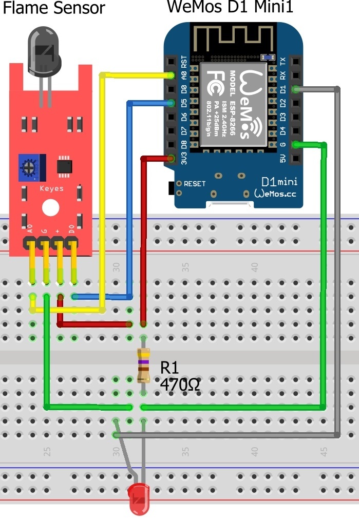
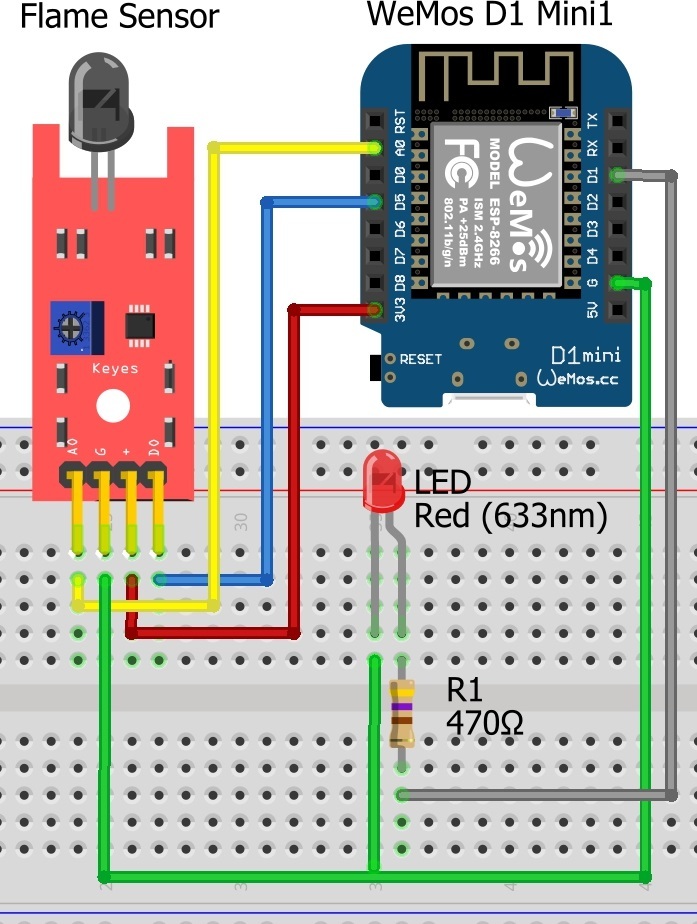
Now swap the buzzer for an LED but the resistor goes between D1 and the LED not GND and 3V3.
I have change the buzzer to LED. The LED always on even the fire is haven’t started but the light very dim.
Resistor is in the wrong place, D1 —> 470R ----> LED. Once we have this working we can work out why the LED is not switching on and off, after this we will put the buzzer back in place. LED’s are great.
Just perfect.
But, the the LED can’t light on.
You keep changing your sketch!!!
Comment out all the Blynk.notify and Blynk.email calls in your sketch as I previously said they can’t be used until you have removed all the bugs from your code and added flame status conditions to stop them being repeated more frequently than every 15s.
Remove all this from setup() as you only have to wait 150ms to be informed if there is a fire.
   // Notify immediately on startup
   if(val==HIGH){
   Blynk.notify("Flame!!!");
   Blynk.email("nurlela.dabukke@gmail.com", "Flame!!!", "Sensor activated");
   //Setup a function to be called every minute
   timer.setInterval(10L, readSensor);
}
Use this for readSensor
void readSensor()
{
  sensor = analogRead(analoog);
  Serial.println(sensor);  // display sensor value
  // You can send any value at any time but don't send more that 10 values per second.
  //Blynk.virtualWrite(V1, sensor);  // if you have a display widget set up on V1 you can uncomment this
  if (sensor < 100) // When the flame sensor detects a signal, buzzer beep
  {
     digitalWrite (buzzer, HIGH);
     // Send email and PUSH messages but max 1 every 15s, logic to be added for this
     //Blynk.email("nurlela.dabukke@gmail.com", "Flame!!!", "Sensor activated");
     //Blynk.notify("Flame detected") + uptime + " minutes.");
  }
     else
 {
     digitalWrite (buzzer, LOW);
  }
 Serial.print("Buzzer state is ");
 Serial.println(digitalRead(buzzer);
  }
When you have done this let me know if the secondary LED on the flame sensor board is going on and off when you add and remove a flame.
Also paste the contents of Serial Monitor (not a screenshot, just paste the data).
I’m so sorry, I forgot to add comment to that line.
I have add comments, and the LED still off when the fire is started. And the content of serial monitor is:
Buzzer state is 0
888.00
Buzzer state is 0
887.00
Buzzer state is 0
888.00
Buzzer state is 0
887.00
Buzzer state is 0
888.00
Buzzer state is 0
889.00
Buzzer state is 0
887.00
Buzzer state is 0
Do you mean the LED attached to D1 or the secondary LED on the flame sensor board?
I’m interested in the LED on the flame sensor board that appeared to be working the other day and giving readings of < 100 in Serial Monitor.
Paste your sketch again.
Both LED are off.
#define BLYNK_PRINT Serial
#include <ESP8266WiFi.h>
#include <BlynkSimpleEsp8266.h>

 // You should get Auth Token in the Blynk App.
 // Go to the Project Settings (nut icon).
 char auth[] = "******************************************";

 // Your WiFi credentials.
 // Set password to "" for open networks.
 char ssid[] = "Redmi 3s";
 char pass[] = "***********";

 int buzzer = D1 ;// define buzzer Interface
 int pin = D0; // define the flame sensor interface
 int analoog = A0; // define the flame sensor interface

 int val ;// define numeric variables val
 float sensor; //read analoog value

 BlynkTimer timer;

 void readSensor()
 {
    sensor = analogRead(analoog);
    Serial.println(sensor);  // display sensor value
    // You can send any value at any time but don't send more that 10 values per second.
    //Blynk.virtualWrite(V1, sensor);  // if you have a display widget set up on V1 you can uncomment this
    if (sensor < 100) // When the flame sensor detects a signal, buzzer beep
 {
    digitalWrite (buzzer, HIGH);
    // Send email and PUSH messages but max 1 every 15s, logic to be added for this
    //Blynk.email("nurlela.dabukke@gmail.com", "Flame!!!", "Sensor activated");
    //Blynk.notify("Flame detected") + uptime + " minutes.");
 }
    else
{
    digitalWrite (buzzer, LOW);
 }
   Serial.print("Buzzer state is ");
   Serial.println(digitalRead(buzzer));
 }

void setup()
{
   pinMode (buzzer, OUTPUT) ;// define buzzer as output interface
   pinMode (pin, INPUT) ;// output interface defines the flame sensor
   pinMode (analoog, INPUT) ;// output interface defines the flame sensor
   // Debug console
   Serial.begin(115200);

   Blynk.begin(auth, ssid, pass);
   // You can also specify server:
   //Blynk.begin(auth, ssid, pass, "blynk-cloud.com", 8442);
   //Blynk.begin(auth, ssid, pass, IPAddress(192,168,1,100), 8442);

   // Notify immediately on startup
   Blynk.notify("Device started");

   // Notify immediately on startup
   //if(val==HIGH){
   //Blynk.notify("Flame!!!");
   //Blynk.email("nurlela.dabukke@gmail.com", "Flame!!!", "Sensor activated");
   //Setup a function to be called every minute
   //timer.setInterval(10L, readSensor);
//}
// Setup a function to be called every 200ms Costas
 timer.setInterval(150L, readSensor);  // Costas
 //Blynk.email("nurlela.dabukke@gmail.com", "Flame!!!", "Sensor activated");
}

void loop()
{
  Blynk.run();
  timer.run();
}
I have cleaned up your code, save this as FlameSensorBad.ino and I will work back through this thread to find the version that appeared to work and we will call this FlameSensorGood.ino
// FlameSensorBad.ino per https://community.blynk.cc/t/create-push-notification-over-flame-sensor/15891/172
#define BLYNK_PRINT Serial
#include <ESP8266WiFi.h>
#include <BlynkSimpleEsp8266.h>

char auth[] = "******************************************";
char ssid[] = "Redmi 3s";
char pass[] = "***********";
int buzzer = D1 ; // define buzzer Interface
int pin = D0;     // define the flame sensor interface
int analoog = A0; // define the flame sensor interface
int val ;         // define numeric variables val
float sensor;     // sensor variable as a float, think it needs to be an int

BlynkTimer timer;

void readSensor()
{
  sensor = analogRead(analoog);
  Serial.println(sensor);  // display sensor value
  if (sensor < 100) // When the flame sensor detects a signal, buzzer beep
  {
    digitalWrite (buzzer, HIGH);
  }
  else
  {
    digitalWrite (buzzer, LOW);
  }
  Serial.print("Buzzer state is ");
  Serial.println(digitalRead(buzzer));
}

void setup()
{
  pinMode (buzzer, OUTPUT) ;// define buzzer as output interface
  pinMode (pin, INPUT) ;// output interface defines the flame sensor
  pinMode (analoog, INPUT) ;// output interface defines the flame sensor
  Serial.begin(115200);  // Debug console
  Blynk.begin(auth, ssid, pass);
  //Blynk.notify("Device started");  // Notify immediately on startup
  timer.setInterval(150L, readSensor);  // Costas
}

void loop()
{
  Blynk.run();
  timer.run();
}
As per the comment I added I think you need int not float for “sensor” but don’t go changing anything yet.
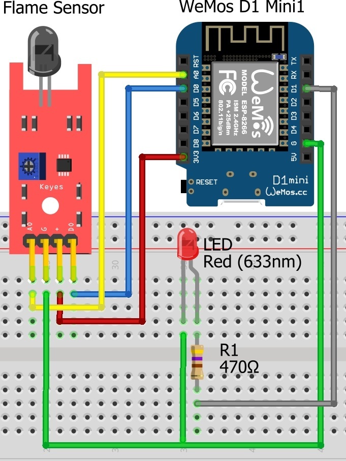
I notice that your Fritzing schematics keep changing and that you were connecting the digital pin of the flame sensor to D0 on the WeMos and now it’s shown as D5.
What is the actual connection on your bread board?
I’m not convinced this digital pin actually does anything other than give a second interface in addition to the analog interface.
Having compared the “good” sketch with the “bad” sketch there is very little difference so I’m going to say you are messing up on the bread board. Stop messing around with the sketch and make sure all the connections are going to the right pins and that you don’t have any loose connections.
Have you actually soldered pin headers on the WeMos or are you trying to do it with a “push fit” header.
The latter generally will not work as I hate soldering and I’ve tried many times with “push fit” headers.
Keep trying until the LED on the flame sensor starts working again and you get new analog values in Serial Monitor. Once this is reliable the LED / Buzzer attached to D1 on the WeMos should be plain sailing.
Sorry, I made wrong schematic diagram cause I remake it. But, in my circuit, D0 pin of sensor still connect to D0 of Wemos.
Any addition with the code? I have tried upload again that FlameSensorGood.ino, but still nothing happened with the secondary LED of the sensor.
Yes.
Have you soldered headers to the WeMos?
You don’t need to do anything with the sketch, keep checking all your connections and add / remove the flame until the flame sensor LED works and Serial Monitor gives different analog values.
Below is the cleaned up “good” sketch. You can try it but I don’t think it’s a problem with the sketch.
/* FlameSensorGoodV1.ino per https://community.blynk.cc/t/create-push-notification-over-flame-sensor/15891/151
 "The value in serial monitor amount 840 and 841 when the fire is off. Whereas the fire is on, the value is amount 40 and 41."   */
#define BLYNK_PRINT Serial
#include <ESP8266WiFi.h>
#include <BlynkSimpleEsp8266.h>

char auth[] = "*********************************************";
char ssid[] = "Redmi 3s";
char pass[] = "***********";
int buzzer = D1 ; // define buzzer Interface
int pin = D0;     // define the flame sensor interface
int analoog = A0; // define the flame sensor interface
int val ;         // define numeric variables val
float sensor;     // sensor variable as a float, think it needs to be an int

BlynkTimer timer;

void readSensor()
{
  sensor = analogRead(analoog);
  Serial.println(sensor);  // display temperature
  val = digitalRead (pin) ;// digital interface will be assigned a value of 3 to read val
  if (val == HIGH) // When the flame sensor detects a signal, buzzer beep
  {
     digitalWrite (buzzer, HIGH);
  }
  else
  {
     digitalWrite (buzzer, LOW);
  }
  Serial.print("Buzzer state is ");
  Serial.println(digitalRead(buzzer));
}

void setup()
{
  pinMode (buzzer, OUTPUT) ;// define buzzer as output interface
  pinMode (pin, INPUT) ;// output interface defines the flame sensor
  pinMode (analoog, INPUT) ;// output interface defines the flame sensor
  Serial.begin(115200);  // Debug console
  Blynk.begin(auth, ssid, pass);
  //Blynk.notify("Device started");  // Notify immediately on startup
  timer.setInterval(150L, readSensor);  // Costas
}

void loop()
{
   Blynk.run();
   timer.run();
}
Actually the sample sketches I have seen are using analog or digital NOT both. I’m not an analog fan so I’m going to provide a new sketch just using the digital pins. Disconnect the wire from A0 on the WeMos and try this:
/* FlameSensorDigitalV1.ino per https://community.blynk.cc/t/create-push-notification-over-flame-sensor/15891/
   Just using digital interface, disconnect wire from AO on the WeMos and watch LED on the flame sensor board   */
#define BLYNK_PRINT Serial
#include <ESP8266WiFi.h>
#include <BlynkSimpleEsp8266.h>

char auth[] = "*********************************************";
char ssid[] = "Redmi 3s";
char pass[] = "***********";
int buzzer = D1 ;   // define buzzer Interface
int pin = D0;       // define the flame sensor interface
//int analoog = A0; // define the flame sensor interface NOT NEEDED
int val ;           // define numeric variables val
//float sensor;     // sensor variable as a float, think it needs to be an int NOT NEEDED

BlynkTimer timer;

void readSensor()
{
  //sensor = analogRead(analoog);
  //Serial.println(sensor);  // display temperature
  val = digitalRead (pin) ;// digital interface
  Serial.print("Digital pin is ");
  Serial.println(val);
  if (val == HIGH) // When the flame sensor detects a signal, buzzer beep
  {
     digitalWrite (buzzer, HIGH);
  }
  else
  {
     digitalWrite (buzzer, LOW);
  }
  Serial.print("Buzzer state is ");
  Serial.println(digitalRead(buzzer));
}

void setup()
{
  pinMode (buzzer, OUTPUT) ;// define buzzer as output interface
  pinMode (pin, INPUT) ;// output interface defines the flame sensor
  // pinMode (analoog, INPUT) ;// output interface defines the flame sensor NOT NEEDED
  Serial.begin(115200);  // Debug console
  Blynk.begin(auth, ssid, pass);
  //Blynk.notify("Device started");  // Notify immediately on startup
  timer.setInterval(150L, readSensor);  // Costas
}

void loop()
{
   Blynk.run();
   timer.run();
}
Then, if I use analog pin, I can’t use buzzer? Cause, I need measure the flame value .
You can still use the buzzer but let’s try to get the LED working (on the sensor board and the one attached to the WeMos).
For reference the trim pot is used to alter the sensitivity of the digital sensor trigger (not analog values).
I think, it’ll better if I remove the buzzer. But, I want to add an LDR and two PIR sensors with LED indicator, how to do it? The condition for LDR and PIR 1 is LED will be on only if there is light and if there is motion. And the condition for PIR 2 is LED will be on only if there is motion. By the way, the analog PIN on my wemos have been used by flame sensor and the LDR use analog pin. Should I change the shield?