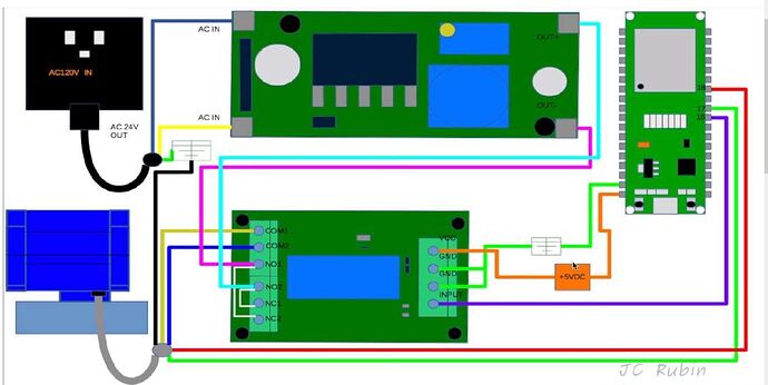
I’ll start by stating I’m completely new at using Blynk, Arduino & ESP32. However, I’ve embarked on a project that will allow me to open and close a water main remotely for a beach condo. Some background on the project. I currently operate the valve via a 2 channel wifi relay set to interlock mode and the ewelink app. Works OK to open or close, but, it does not provide feedback on the status (open/closed/midway) of the valve. For this project I will be using a 120vAc to 24vDC power supply for the valve, a 5vdc DPDT relay to switch polarity and ESP32 to control it. The valve has 5 wires, 2 to open and close the valve and three to Illuminate LEDs when the valve has fully opened or has fully closed. The project I found does not use physical LEDs to display the status, but I may want to use them on site as a visual representation of the status.
I did some digging and found someone who wrote the code for this exact valve for an irrigation project. A full description and the code is available on github by searching ‘Ballvalve’ or here if the link is allowed. I’ve also attached schematic of the connections. I can cut and paste the code to the forum if needed.
I can upload this code and run it, but would not want to use the Arduino IDE to always operate it. My question is, can I incorporate Blynk to this existing code in order to add mobile connectivity and control to this project ? Do I create the blynk interface and just add it to the existing code? If so, could someone point to some tutorials on how that’s done. Or do I have to start from scratch and write new code just because I’m using Blynk (If so this will take much longer as I would need to learn how to rewrite this code for blynk)
In Blynk, I would essentially have a single button for on (open) and off (closed) (this toggle would need to reverse the polarity) with a second ‘display’ of some sort that shows the valve did OPEN, did CLOSE or is MIDWAY (did not open or close after a set period of time based on Jordan’s code)
Would also like some opinions on the addition of physical LEDs. In the attached schematic, The valve’s black wire is connected directly to the AC24V ground, which I don’t have as I will go from 120v AC to 24vdc and the schematic does not use LEDS for display.
The manufacturer has:
- One leg of each LED connected directly to ‘+’ side of a 24vDC power supply
- The second leg of each LEDs connected directly to the Red or Green valve wires (which in
this project go to directly to ESPs 17 pin [Grn] and 18 pin [Red]) - The valves Black wire connecting directly to ‘-‘ side of 24vDC Power supply
- The valve operation works by switching the polarity to the yellow and blue wires, which will open or close it
Do I need any resistors to add the LEDs, or can I just connect directly to the board (17 & 18) and ‘-‘ side of the 24vDC power supply as stated above?
Thanks for reading and any help that is provided !

 Not sure how to get this to work (blynk settings or sketches) I figure, once I get this working, I’ll play around with adding physical LEDs at a later time. Any help on getting this to work properly is greatly appreciated !!