@Blink_tynker I’ve just edited the code in my last post to fix the error that I mentioned here:
which I forgot to do earlier.
Pete.
@Blink_tynker I’ve just edited the code in my last post to fix the error that I mentioned here:
which I forgot to do earlier.
Pete.
Eureka Pete! Thanks for the code lesson … that update worked, the appropriate virtual LEDs are on when it’s either open or closed and both are on when the valve is changing state … which I guess is a good indicator that it’s either moving or stuck. Now that I have this working, I’m looking at updating the code to include the addition of physical LEDs. Seems like I would just add the new #defines for open & closed additional lines plus the new pinModes
'# define realLEDOpen = xx // what ever pin I connect the LED to & GND
'# define realLEDClosed = xx // what ever pin I connect the LED to & GND
pinMode(realLEDOpen,OUTPUT) // add under void setup
pinMode(realLEDOpen,OUTPUT) // add under void setup
then right below the ‘Blynk.virtualWrite’ lines, add new digital write lines to turn the physical LEDs on
if (digitalRead(openPositionGPIO) == HIGH)
  {
    Blynk.virtualWrite(v_openLED,255);
    digitalWrite (realLEDOpen,HIGH); //new lines to turn on open Real LED on when valve is open
  }
  else
  {
    Blynk.virtualWrite(v_openLED,0);
    digitalWrite(realLEDOpen, LOW); // new lines to turn off open Real LED off when valve is closed
  }
and then duplicate this for the closed LED
I don’t have any LEDs at the moment, can’t actually test this … but it looks like GPIO21 and GPIO22 can be used for each LED. Any suggestions on an LED kit to use, I found this kit on Amazon seems like it has what I need, I guess I just need to match the correct resistor with the Red and Green LEDs
The code looks good!
As far as the LEDs are concerned, I’d prefer to have LED that a proper specification for their voltage, current consumption, brightness etc, to allow you to accurately calculate the value of the series resistor.
The kit you linked to doesn’t even say what size the LEDs are.
Pete.
Hi Guys, I’m tweaking my setup a little and have a few questions. I going to add a DPDT bypass switch between my relay and the valve. This switch will toggle the source of power to the valve from either the valve relay when it’s in the up position or from a second DPDT switch (wired to reverse polarity) when it in the down position. This way I have a backup switch if the ESP32 and/or relay ever fail and I need to open and close it with a manaul switch.
I’ve also decided to upgrade my current water heater wifi setup from the current wifi on/off switch and app, to a second relay connected to the ESP32 and turning it on and off fith a second virtual button in Blynk … this will also have switch to toggle the activation source for the contactor that powers the Water Heater (Up: Relay controls contactor, middle power off, Down: Switch powers contactor) I’ve added in the new code and have no errors.
My Question:
My current set up is for the ESP32 to illuminate physical LEDs via separate GPIO outputs and virtual LEDs in Blynk when another set of GPIO INPUT pins sense a GND signal from either the red or green valve wires. However, if I’m in manual mode and the ESP32 and relay(s) are down, there would be no physical LED illumination on site as the ESP32 (the LED power source) would be down. Looking for some ideas to Illuminate the physical LEDs from a separate source – maybe the 24vDC valve power + resistors – and still have the ability to illuminate virtual LEDs when the system is online (ESP32, relay and Blynk)
Do I just read power off of the separate LED power source on a GPIO same as the ground read and add a resistor in between ?
.
For the water heater, I just want a physical LED indicator, so I can add an LED + resistors to work with 120v which will tell me if power is flowing to the contactor or not. I do have a question on this, if I have a 2v, 20mA LED, it appears that a 6.2KΩ resistor is required. I have smaller and larger ones, but the closest to 6.2K I have are 5.1K and 10K. Do I just combine a 100Ω, 1KΩ and 5.1KΩ in series to get the 6.2k ?
Thanks, Jack
I’ll answer the last question first…
Yes, you can add resistors in series to make the value you want, or just go for the next higher value.
However - LEDs are DC devices and powering them from mains AC won’t give a very satisfactory result. The LED will only be receiving forward voltage half of the time (because the AC reverses polarity at a frequency of 60Hz in the US, 50Hz in the civilised world). This means that your LED will appear dimmer than expected, and will have a reverse voltage applied to it for 50% of the time, which isn’t conducive to a long life for the LED. You can probably buy LEDs that are designed for 120v mains, which include a bridge rectifier circuit and built-in resistor.
Back to the first question - I think I understand what you’re asking, and I’d recommend using an option isolator between the 24v supply and the GPIO pins of the NodeMCU. This lowers the risk of a component failure resulting in a fried ESP32, and will also help eliminate electrical noise from the 24v valves.
Pete.
Thanks, Pete. Yes, they do. I’ve already looked and found them, then thought I could use existing LEDs, but it sounds like it’s a better Idea to just get the ready made ones.
Not familiar with this, can you provide me with some more information on what this is or a link to one.
Thanks, Jack
Is option isolator the same as an optocoupler ?
Sorry, my spell check butchered what should have been “Opto Isolator”.
Yes, sometimes referred to as an optocoupler.
Basically an LED and a phototransistor in a package which provides electrical isolation between two circuits.
Pete.
Ok I did some reading on these, looks like I need two of them, – one for each LED?
I do have 12-24vDC LEDs, so additional resistors should not be required to power them
If I were to use the Sharp PC817, I would connect (although I’m not sure if I need to add any resistors on the 24vDC side and/or on the ESP32 side of the octo coupler connection)
Optocoupler #1 (Open)
Optocoupler #2 (Closed)
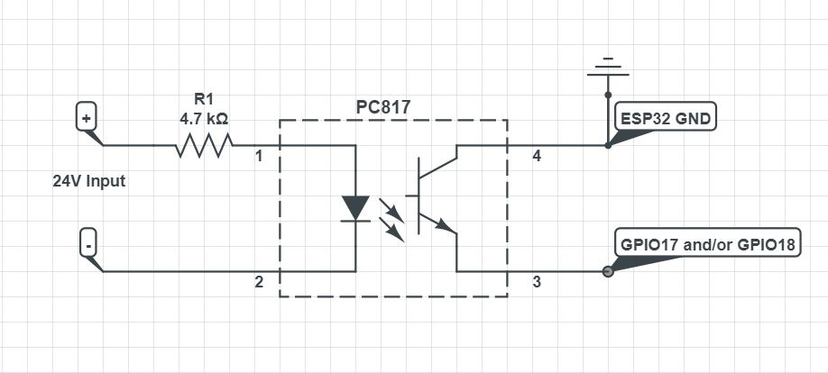
Hi Pete, looks like this is the connection I need to make … does this look right ?
Two PC817s, for each connect to1,2,3 have the same connection with #4 going to GPIO 17 for the open vLED and the other #4 going to GPIO 18 for the closed vLED
Thanks, Jack
Do you mean pin #4 of the PC817, or do you mean pin #3 ?
Pete.
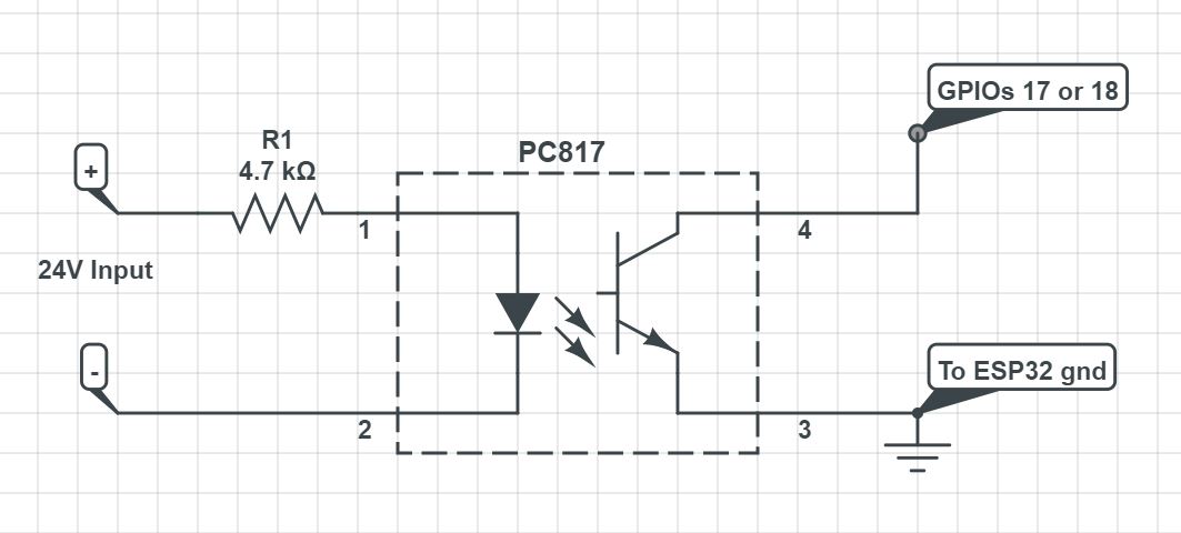
oops my mistake … it’s as written (Schematic was wrong) Pin 3 to GND and pin 4 to the GPIOs …
updated the schematic
I thought pin #4 was supposed to be GND?
Pete.
This where I’m a getting little confused when reading, I’ve seen it written both ways but this way seemed to fit what I was attempting to do.
Although I’m making the assumption that this will essentially work as a switch for me, when the diode has ‘-’ power applied (via the valves internal open/close switch) and the pc817 LED is on, a connection is made between the Emitter and collector …essentially connecting the ESP32’s ground to the appropriate GPIO pin, where my code will read it and illuminate the appropriate vLED… Or maybe I have that completely wrong
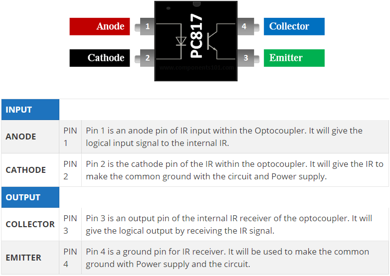
I was goiung by this:
But I’ve now realised that the diagram labels pin 4 as the Collector, but the description below labels it as the Emitter!!
I’d suggest that you dig-out the manufacturers datasheet and follow that.
Pete.
ahh I see … that’s why we get confused LOL
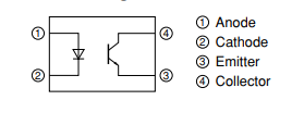
Here is the data sheet
It has pin 3 as emitter and pin 4as collector …
So then I guess its pin 3 (emitter) to GND and pin 4 (collector) to the GPIOs
Since I’m still using INPUT_PULLUP, I’m assuming I don’t need a resistor between pins 3 or 4 and the ESP32 as it should work the same way I currently have it set up – GND to valve switch to GPIO … except with this, its GND to PC817 to GPIO, with the PC817 now acting as the valve switch to illuminate the vLEDs after the real valve switch sends current through the PC817
That sounds like a reasonable assumption. I assume that you’ve calculated your 4.7K resistor based on your 24V supply voltage and the datasheet?
Pete.
correct
// Fill-in information from your Blynk Template here
#define BLYNK_TEMPLATE_ID "TMPLBxxxxxxx"
#define BLYNK_DEVICE_NAME "Water Switches"

#define BLYNK_FIRMWARE_VERSION        "0.1.0"

#define BLYNK_PRINT Serial
//#define BLYNK_DEBUG

#define APP_DEBUG

// Uncomment your board, or configure a custom board in Settings.h
//#define USE_WROVER_BOARD

#include "BlynkEdgent.h"
#define valveRelay 16
#define whRelay 26
#define openPositionGPIO 17
#define closedPositionGPIO 18
#define openLED 21
#define closedLED 22
#define whLED 23
#define vRelayBtn V1
#define v_openLED V2
#define v_closedLED V3
#define vWHBtn V4

void control_LEDs()
{
  if (digitalRead(openPositionGPIO) == HIGH)
  {
    Blynk.virtualWrite(v_openLED,255);
    digitalWrite (openLED,HIGH);
  }
  else
  {
    Blynk.virtualWrite(v_openLED,0);
    digitalWrite (openLED,LOW);
  }


  if (digitalRead(closedPositionGPIO) == HIGH)
  {
    Blynk.virtualWrite(v_closedLED,255);
    digitalWrite (closedLED,HIGH);
  }
  else
  {
    Blynk.virtualWrite(v_closedLED,0);
    digitalWrite (closedLED,LOW);
  }
}

void setup()
{
  // Debug console
  Serial.begin(115200);

  pinMode(valveRelay,OUTPUT);
  pinMode(openPositionGPIO,INPUT_PULLUP);
  pinMode(closedPositionGPIO,INPUT_PULLUP);
  pinMode(openLED,OUTPUT);
  pinMode(closedLED,OUTPUT);
  pinMode(whRelay,OUTPUT);
  pinMode(whLED,OUTPUT);

  BlynkEdgent.begin();
}

BLYNK_WRITE(vWHBtn)
{
  if (param.asInt())
  {
    digitalWrite(whRelay, HIGH);
    digitalWrite(whLED,HIGH);
  }
  else
  {
    digitalWrite(whRelay, LOW);
    digitalWrite(whLED,LOW);
  }
}
BLYNK_WRITE(vRelayBtn)
{
  if (param.asInt())
  {
    digitalWrite(valveRelay, HIGH);
  }
  else
  {
    digitalWrite(valveRelay, LOW);
  }
}
void loop()
{
  BlynkEdgent.run();
}
Hi guys, I’m migrating this to Blynk 2.0 … my buttons in the app seem to work OK to turn each relay on and off, but, I can’t get it to display the virtual led (on/off) in the app …I feel like I’m missing something in the web dashboard of blynk console …
for instance, on the open LED I have Pin=V2, Data Type =Integer, Units=None, Min=0, Max =255(also tried min0/max1) and default value = null
255 should work.
Have you tried adding a display widget attached to the same datastream to see what values you are sending to that datastream?
The Max value of the datastream actually defines what value will give the maximum brightness level of the LED widget. So, if you have a datastream attached to an LED where that datastream’s Max value is 255 and you write 255 to that virtual pin then the LED will be on at full brightness.
If you then change the datastreams Max value to 1023 and deploy the changes, a value of 255 will result in 25% brightness. You would then need to write 1023 to the virtual pin to give maximum brightness.
Pete.