i iam using 4 switch in blynk app to turn on and off 4 pins i want connect 2 switch on two pins of esp 8266nod mcu and use led indicator on blynk app please for god sake some one please make example code for me to do this iam using esp8266 example standalone code and iam at learning stage please help me please
Please, for our sake, use proper grammar and punctuation ![]()
Then use the Search and read functions of this forum. You can also checkout the Documentation, Help Center and Example Sketches… all those links are at the top of this page.
dear i want to use both function read and receive at the same time. how it will work please help
please share code so can understand how it work its my first project on iot fustrated things not working so any one please share code or tutorial so i can follow will be very thank full to this fourm
want to add led indicator on blynk app with these button whic will light up when i press push button on nod mcu d0 and d1 how it will work please help
I already provided two links above… one for reading the status of a button/switch (physical) with a Widget LED, and another to synchronize the state of both a physical button and a Widget button… and there are lots more examples where those came from.
dear can i combine these code will it work at same time send and receive what will be the code
thanks i have gone through this but these code work only one at a time
for switch i have to ground pins
Of course… they are just examples. Once you get past the basic Blynk examples you need to do lots of reading and experimenting in-order to learn how the commands work and how add them together to make your projects work.

We can try to assist with suggestions and some guidance… but we can’t teach you or do it for you. We are just fellow Blynk users and volunteers, and we have our own projects and lives.
Umm, sure… depends on what and how you want to physically hook them up. Google for the various ways to wire in a button or switch (technically same thing at far as the GPIO is concerned) with either pull-down or pull-up resistors, depending on your need to drive a GPIO HIGH or LOW on button press.
For example…
i want to use digital pins as input
and digital pin as output
You are in good hands then with an ESP8266… they have GPIO (General Purpose INPUT & OUTPUT) pins
And Blynk has documentation showing how to use them…
etc…
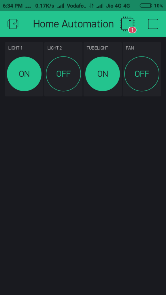
thanks gunner for sharing this i just want to do same thing pressing switch physicaly but led should light up on blynk app. iam not geting to work out on blynk physically its doing good as shown
i have manage to made a working code just want little help i want to add one more widget to get data from pin D5 and display it on virtual pin v4 in this code its not working please help
/* Comment this out to disable prints and save space */
#define BLYNK_PRINT Serial


#include <ESP8266WiFi.h>
#include <BlynkSimpleEsp8266.h>

// You should get Auth Token in the Blynk App.
// Go to the Project Settings (nut icon).
char auth[] = "";

// Your WiFi credentials.
// Set password to "" for open networks.
char ssid[] = "";
char pass[] = "cyber2018";

// Select your pin with physical button
const int btnPin = 4;

WidgetLED led3(V3);

BlynkTimer timer;

// V3 LED Widget represents the physical button state
boolean btnState = false;
void buttonLedWidget()
{
  // Read button
  boolean isPressed = (digitalRead(btnPin) == LOW);

  // If state has changed...
  if (isPressed != btnState) {
    if (isPressed) {
      led3.on();
    } else {
      led3.off();
    }
    btnState = isPressed;
  }
}

void setup()
{
  // Debug console
  Serial.begin(9600);

  Blynk.begin(auth, ssid, pass);
  // You can also specify server:
  //Blynk.begin(auth, ssid, pass, "blynk-cloud.com", 80);
  //Blynk.begin(auth, ssid, pass, IPAddress(192,168,1,100), 8080);

  // Setup physical button pin (active low)
  pinMode(btnPin, INPUT_PULLUP);
  pinMode(D1,OUTPUT);
  pinMode(D7,OUTPUT);
  pinMode(D3,OUTPUT);
  pinMode(D4,OUTPUT);

  digitalWrite(D1,HIGH);
  digitalWrite(D7,HIGH);
  digitalWrite(D3,HIGH);
  digitalWrite(D4,HIGH);

  timer.setInterval(500L, buttonLedWidget);
}

void loop()
{
  Blynk.run();
  timer.run();
}
I fixed your post… you need to properly format any posted code as per the directions…
Probably becasue you are not actually doing anything to send data to any widget on V4… Please read!!
i have used one widget and geting switch data from d2 pin on nodmcu and lighting up led connected with virtual pin v3 as per code in blynk app i want to add another switch on pin d5 on nodmcu and led on virtual pin v4 in blynk in the same code not doin right please help with my code i you can .
It appears that you are not even trying…
Sorry, I am not writing your code for you. There is plenty of perfectly good documentation and examples for such simple processes… if you will not read, I will not bother pointing them out any further.
dear gunner i have already made the code just want addition
Dear @Peacefinder… I deleted your repetitively posted but still unformatted code.
If you can’t even follow those simple directions, let-alone do some reading and learning of your own, despite being handed all the instructions, then this topic will soon be closed.