Thanks for your help, I’ll give that a try tomorrow. Still wish I could find why using V0 worked when V1 didn’t though, if only to try and help me understand how to use virtual pins in the future.
Thanks, I need to read up a bit more to understand this. I’m using Apple shortcuts which works very similar to callling IFTTT and I want it to work with that.
By the way, I used the Darlington array because the video I watched said the output from the D1 Mini was not sufficient to drive the relays, this was incorrect then? The voltage regulator is there because in situ the board will be stealing power from the garage door control box rather than using USB power supply.
Andy
The type of relay that you (and I) are using is designed for use with boards like the Wemos. It has all the circuitry, including optoisolators, on the board already.
I like @Toro_Blanco’s idea of adding-in a Blynk-virtualWrite to switch the pushbutton back if you’re using the API calls.
Pete.
Thanks I can use a much smaller board then. I’m really baffled now, I’ve uploaded your code and it works exactly the same as mine, whether I use the Blynk app or Shortcuts. If I change the button away from V0 it doesn’t work. However, I notice if I change the button to V1 and press it, the blue light on the Wemos momentarily goes off which doesn’t happen otherwise.
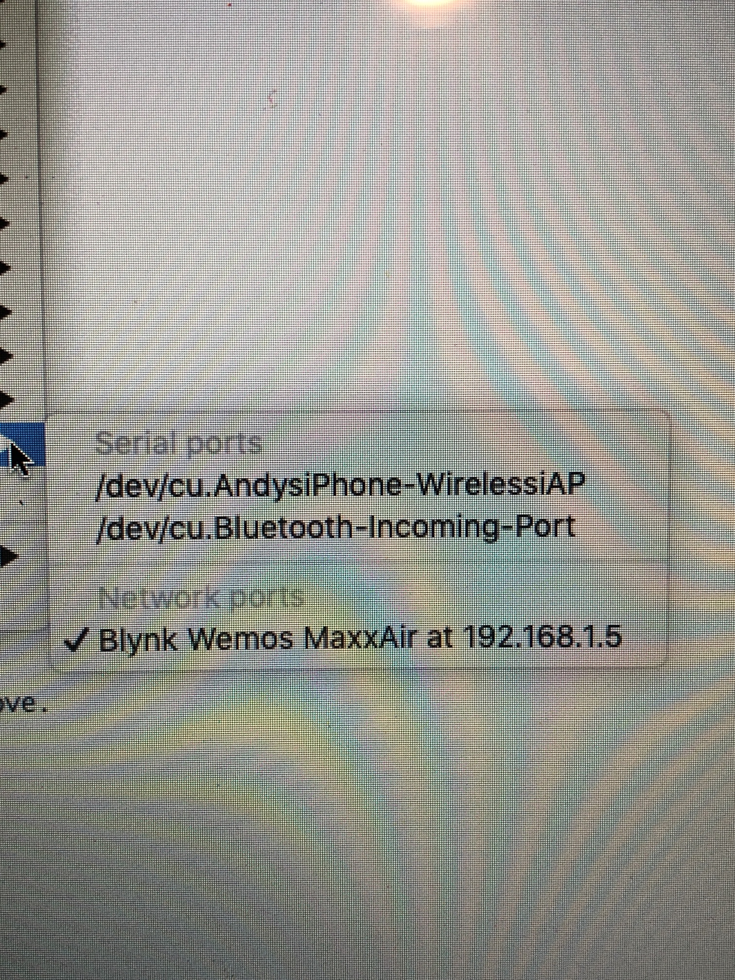
ETA, If I try and read the Serial Monitor I get this error
Serial monitor is not supported on network ports such as 192.168.1.5 for the null in this release
Your original code had some OTA libraries installed, but none of the code necessary to initiate or use OTA updates.
The serial monitor error message is because you are uploading the code to your device via an OTA port, but (unless you’re running different code to what you posted) it’s not possible to upload to the board in this way.
Do you have more than one Wemos?
Is it possible that you’re uploading your code to a different device (this could explain a lot!)?
To upload without OTA, and to use the serial monitor, select the COM port that your Wemos is connected to.
Pete.
BTW, it’s always good to solder 0.1” socket strips to your board to accept the pins you’ve soldered to the Wemos. That way it’s easy to pull the Wemos in case of any issues.
Pete.
1 Like
I don’t have any other Wemos devices, or anything similar, I ordered this one just to do this project. The usb com port was there when I first programmed it but hasn’t appeared since.
The “MaxxAir” name was just because that’s what the original piece of code I pinched was controlling and it set to that name.
Good point
Is this a Mac?
Pete.
Yes
Andy
Okay, don’t know to select the COM port then.
In the Windows version of the IDE it appears when you you plug the Wemos in an will say something like COM14
Pete.
I think you’ve identified the issue here, I’ve just changed the delay on the door2 subroutine to 10 secs and even though it says “Done Uploading” without any errors, it still has the same 1 sec delay as before. It looks like when I think I’ve changed the code, it hasn’t changed anything at all, I could be running a much earlier iteration of what I had. I’m going to have to sleep on this, up early for work tomorrow. Thanks for your help and patience.
Aargh, an earlier version of the module had these lines in that I deleted as they didn’t seem to affect the operation, so I assume this means that every edit since then has done nothing! I feel a proper idiot now. I’ll put them back.
#include <ArduinoOTA.h>
/// .......

ArduinoOTA.handle();Yep, that’s the stuff I was talking about to initialise and use OTA updates.
To put these lines back you need to use a serial port rather than an OTA network port.
Pete.
Ok we can close this now, you’ve helped me narrow down what the problem was. It turned out to be the USB cable. After I programmed it initially and ended up removing the OTA code, I took the setup to the garage to connect up and test, in doing so I picked up a power bank and a shorter cable to make it easier to carry, and yes it turns out it was a power only cable so that when I came back in and plugged it back into the Mac all subsequent changes I made never happened. So you were right, it wasn’t actually runing the code I had posted at all, hence why the changes suggested to me didn’t alter how it ran. Went back to the original cable and up popped the serial port.
I feel a bit of an idiot, but in my defence , as the “Done uploading” text appeared afterwards with no error message, I had no reason to assume it hadn’t worked. The code you suggested runs perfectly and I have now tidied it up to V1 and V2 for neatness. Sorry for wasting peoples’ time but I’m glad I understand it now and I’ll make sure to read up and experiment when my reed switches arrive and see if I can work it out myself. Thanks again to both for your help.
Andy
Hey Andy, no problem at all.
I’ve certainly done things that are equally as stupid, but it’s all part of the learning process - provided we don’t have a Homer Simpson moment and have to forget something equally as useful to make room for this new bit of knowledge!
The main thing is that your confidence with the device grows the more you mess around with it and it starts to become a little less scary.
As I said before, you’ll need to add some sort of switches to detect when the doors are opened or closed.
These will be connected to physical pins on the Wemos, and you’ll probably use an LED widget to show when the door is open or closed.
When it comes to adding these switches, take care which pins you choose. This is a very handy reference, and as you can see there are some pins that will prevent the Wemos booting-up and running normally (GPIO0 and 15 [D3 and D8] for example)…
Give us a shout when you get to that stage, even if it’s just a sanity check before you go any further.
I’d recommend ordering a couple more D1 Mini Pros from China, along with a couple more of the relay boards that you’re using. The’ll take a while to arrive on a slow boat, but the you’ll have some spares that you can test code and additional hardware setups on in an off-line environment and also as spares to swap-out if you need to do some troubleshooting.
You might also find this topic of interest:
I have a project where I’ve also stolen some power from a door entry system and that is described a little in that topic. I put my voltage regulator on a Wemos prototyping board and used a triple base to mount it, but a double base and the external relay board would well for you.
I’ll mark this as “Solved”, but the topic is still open and you can still post here if you wish.
Cheers,
Pete.
Thanks Pete, some interesting reading there. I’ve already ordered some more D1 Pros and relays, along with a couple of external antennae as the garage is very iffy for wifi signal. I’ve also ordered a pack of magnetic reed switches so that will be the next step.
1 Like
Don’t forget that you need to move the tiny resistor if you want to use an external antenna. Some photos in the topic I linked to.
Pete.
1 Like
Well that didn’t go as planned, the day after I last posted this I started with a heavy cough which turned nasty in a 2 days and I ended up with 4 days in hospital, though thankfully not on a ventilator. I’ve finally felt well enough to get my rather fuzzy head round this and in the last few days I’ve got to grips with it and now have this fully working. The Blynk app has two buttons for the doors with an LED widget next to each one that shows green when closed and red when open. When I have time and inclination I’ll investigate how to use the colour of the button itself to show status without the LED widgets, but for now this works so I’m a bit reluctant to fiddle with it. Thanks again for the help.
By the way, I’m now using a NodeMCU as I actually stood on the Wemos during a coughing fit and broke it. More of them are on the way from China but it’s taking an eternity so I managed to get a couple of NodeMCUs from Amazon to use in the meantime. I will swap it out when the Wemos arrives though, the WiFi signal sometimes drops off as it is and I could do with the ability to connect the external antena.
#define BLYNK_PRINT Serial
#include <ESP8266WiFi.h>
#include <BlynkSimpleEsp8266.h>


char auth[] = "do";
// Your WiFi credentials.
char ssid[] = "VodafoneConnect";
char pass[] = "";

WidgetLED led1(V3); // declare which pins to use for virtual LED widget
WidgetLED led2(V4);

BlynkTimer timer;

// constants won't change. They're used here to set pin numbers:
const int door1RelayPin = 4; // D2
const int door2RelayPin = 5; // D1
const int door1SensorPin = 13; // D7
const int door2SensorPin = 12; // D6
int door1Status;
int door2Status;

#define BLYNK_GREEN     "#23C48E"
#define BLYNK_RED       "#D3435C"


void setup()
{

 pinMode(door1RelayPin, OUTPUT);
 pinMode(door2RelayPin, OUTPUT);
 pinMode(door1SensorPin, INPUT_PULLUP);
 pinMode(door2SensorPin, INPUT_PULLUP);


 digitalWrite(door1RelayPin,LOW); // ensure relays not activated on power-on
 digitalWrite(door2RelayPin,LOW);


 Serial.begin(74880);

 led1.on(); // Turn LED widgets on
 led2.on();
 timer.setInterval(1000L, LED1Widget); // Call each subroutine every 1 second
 timer.setInterval(1000L, LED2Widget);
 Blynk.begin(auth, ssid, pass);  //connects to the blynk server using the credentals from above.

 }


 // Door 1 LED Widget
void LED1Widget()
{
  door1Status = digitalRead(door1SensorPin); // Get the reed switch status
  if (door1Status) // if it's HIGH then do this...
  {
    Serial.println(door1Status);
    led1.setColor(BLYNK_RED);
    Serial.println("LED on V3: red - Door 1 open");
  }
  else // if it's LOW then do this instead....
  {
    Serial.println(door1Status);
    led1.setColor(BLYNK_GREEN);
    Serial.println("LED on V3: green - Door 1 closed");
  }
}

// Door 2 LED Widget
void LED2Widget()
{
  door2Status = digitalRead(door2SensorPin); // Get the reed switch status
  if (door2Status) // if it's HIGH then do this...
  {
    Serial.println(door2Status);
    led2.setColor(BLYNK_RED);
    Serial.println("LED on V4: red - Door 2 open");
  }
  else // if it's LOW then do this instead....
  {
    Serial.println(door2Status);
    led2.setColor(BLYNK_GREEN);
    Serial.println("LED on V4: green - Door 2 closed");
  }
}


BLYNK_WRITE(V1)
{

  if (param.asInt() == 1) // DOOR 1 MODULE
  {
    digitalWrite(door1RelayPin, HIGH); //Close the relay
    Serial.println("Relay 1 Activated");
    delay(500);
    digitalWrite(door1RelayPin, LOW); //Release the Relay
    Serial.println("Relay 1 Deactivated");
    Serial.println("");
  }

}

BLYNK_WRITE(V2)
{

  if (param.asInt() == 1) // DOOR 2 MODULE
  {
    digitalWrite(door2RelayPin, HIGH); //Close the relay
    Serial.println("Relay 2 Activated");
    delay(500);
    digitalWrite(door2RelayPin, LOW
    ); //Release the Relay
    Serial.println("Relay 2 Deactivated");
    Serial.println("");
  }

}

void loop()
{
  Blynk.run();
  timer.run();
}