First time I’ve tried using Blynk. I’m trying to use the app to control a Wemos D1 Mini Pro activating relays to close 2 garage doors. The code is using Arduino IDE and is adapted from someone else’s and I’ve stripped out anything that had no effect to make it smaller. It’s controlled from my iPhone by sending a 1 or a 0 via the Get Url command.
This works in as much it activates the relays, but although I’m using V1 and V3, only the V3 part works as it should, the V1 part ignores the time delay (put in to create a 1 sec pulse) and for someone reason will only trigger if I call V0 in the the Get URL call rather than V1. What am I doing wrong?
#include <Blynk.h>
#include <ESP8266WiFi.h>
#include <ArduinoOTA.h>
#include <WiFiUdp.h>


bool current = 0;
bool previous = 1;


// constants won't change. They're used here to set pin numbers:
const int door1 = 2;
const int door2 = 1;

int Door1State = 1;
int Door2State = 1;

char auth[] = "";

// Your WiFi credentials.
// Set password to "" for open networks.
char ssid[] = "";
char pass[] = "";


void setup()
{

  pinMode(D1, OUTPUT);
  pinMode(D2, OUTPUT);


  Blynk.begin(auth, ssid, pass);  //connects to the blynk server using the credentals from above.

  Blynk.syncAll();

}


 BLYNK_WRITE(V1)
{
      if (param.asInt() == 1 && Door1State == 0){            // DOOR 1 MODULE
      Door1State = 1;
      digitalWrite(door1, HIGH); //Close the relay
      delay(1000);
      digitalWrite(door1, LOW); //Release the Relay
      }
      if (param.asInt() == 0 && Door1State == 1){
      Door1State = 0;
      digitalWrite(door1, HIGH); //Close the relay
      delay(1000);
      digitalWrite(door1, LOW); //Release the Relay}
      }
}

BLYNK_WRITE(V3)
{
      if (param.asInt() == 1 && Door2State == 0){            // DOOR 2 MODULE
      Door2State = 1;
      digitalWrite(door2, HIGH); //Close the relay
      delay(1000);
      digitalWrite(door2, LOW); //Release the Relay
      }
      if (param.asInt() == 0 && Door2State == 1){
      Door2State = 0;
      digitalWrite(door2, HIGH); //Close the relay
      delay(1000);
      digitalWrite(door2, LOW); //Release the Relay}
      }
}


void loop()
{
  Blynk.run();

}
Would you like to clarify where this GET API call fits into the equation?
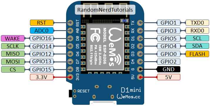
I’m confused about which pins you are using for your relay.
The PIN numbers you define in your constants are GPIO pins 1 and 2. These are different from the ‘D’ PIN numbers that are printed on your Wemos.
Sorry, the Get API is when I’m triggering it with Apple Shortcuts (http://cloud.blynk.cc/auth/update/V0?value=1) but using the buttons in the Blynk app works exactly the same ie the subroutine for door2 works perfectly, but the subroutine for door1 only works if I use the button to trigger V0 and even then it ignores the delay
Exactly, that’s what I can’t understand. Only the second subroutine worked and calling V1 did nothing. After I ran out of other ideas I tried changing the virtual pin no and found when I got back round to V0 that it triggered the relay on/off as in the subroutine, but I don’t understand why, or why it then ignores the delay. The pulse is still long enough to trigger the garage door to open, but it certainly isn’t 1 sec as in the second subroutine.
@llawsa, I tried running this code on a Wemos D1 Mini Pro and I couldn’t even get your code to compile.
I’ve fixed that now and made some changes, but I need to know a bit more about your relays etc.
Are your relays activated when a LOW signal is applied, or a HIGH signal?
Presumably, you need the relay to close the contacts for 1 second to start the door operating?
Does this open the door? If so, how do you close it?
Are your button widgets set up as Push or Switch?
Edited to add, the reason for asking is that i’m Trying to avoid the doors activating when the Wemos resets.
Thanks for your responses. That’s odd, it compiles and runs fine at my end, the only things I removed were the authentication code and my wifi credentials.
My relays are connected to the pins on the Wemos marked D1 and D2, via a Darlington array. They are activated on a LOW signal.
The intention was to set the on time for 1 second in order to activate the doors, but in fact even the much shorter time I’m getting on door1 is enough when I trialled it, so as it stands the sketch does what I want it to, I just can’t understand why. It was taken from a much bigger sketch shown on a Youtube channel called Everlanders, where the guy showed his much more complete sketch controlling almost everything in his RV via Blynk. I looked at this sketch and decided I’d like to have a go at IOT and found a subroutine that I thought would operate my garage doors. I actually put the door2 section in first and it worked prfectly. I then copied and pasted it above to operate door 1, changed the values appropriately and it didn’t work. Until I stumbled across V0.
The buttons are both set up as Switch, so I can see the current state (though this is unchecked, when I learn a bit more I want to incorporate sensors to confirm position).
The doors are effectively a toggle, so sending the opposite state will close them.
digitalWrite(door1, HIGH); //Close the relay
digitalWrite(door2, HIGH); //Close the relay
Pin 2, that is door1 would be the pin labeled D4 on the Wemos Board.
Pin 1, that is door2, would be the pin labeled TX on the Wemos Board.
D1 is GPIO5, and D2 is GPIO4. So you should have
const int door1 = 4;
const int door2 = 5;
along with this in your setup()
void setup()
{

  pinMode(4, OUTPUT); // or pinMode(door1, OUTPUT);
  pinMode(5, OUTPUT); // or pinMode(door2, OUTPUT);

  Blynk.begin(auth, ssid, pass);  //connects to the blynk server using the credentals from above.

  Blynk.syncAll();

}
I see why you had a problem compiling it now, I had somehow added this line
“”"#include <Blynk.h>"""
presumably after scouring other peoples code to see if it made a difference and never got round to compiling it. I’ve removed it now and it runs as before.
Thanks, I understand why I should have done that and I’ll remember next time, but it still runs exactly the same - door1 subroutine quickly clicks the relay on/off when the V0 button is pressed, door2 clicks the relay with a 1 sec delay between each pulse when the V3 button is pressed.
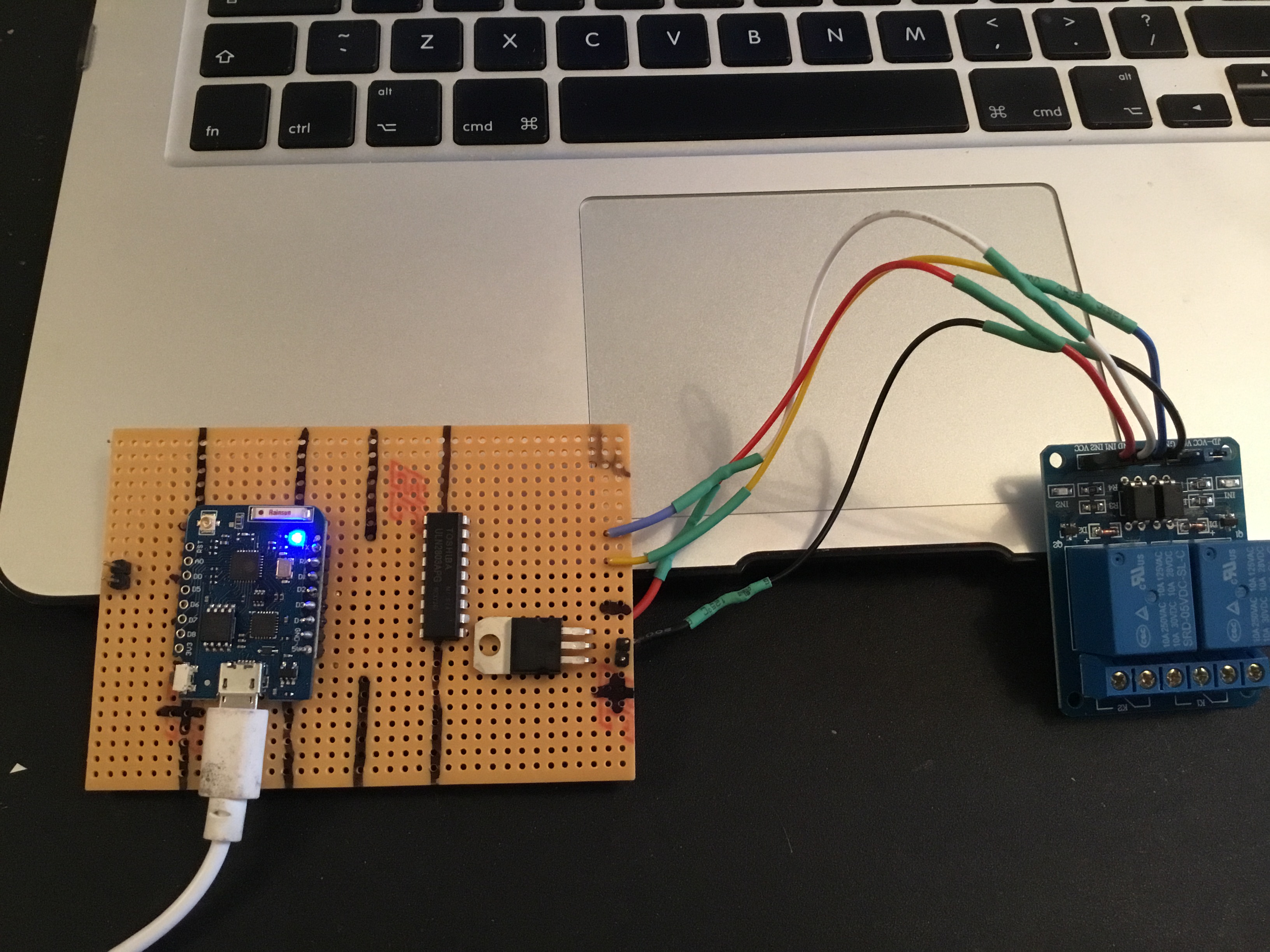
Can you post a photo of the board and it’s connections (not that we don’t trust you of course, it’s just that I can see no way how this can work, and it doesn’t work for me with the same hardware ).
I’ll post some working code soon, when I’ve played-around with Switch rather than push button widgets.
Okay, I can’t see how the circuit is wired from the photo, but I can tell you that most of the hardware on the board is redundant.
I’ve done my testing like this, complete with NHS Rainbow
Using the button widgets in switch mode is a bad idea. Depending on the status of the doors when you power-up the Wemos, they could be showing the exact opposite of the actual situation. Because of this, I’ve changed them to Push operation in my version of the app.
Because your doors toggle rather topen/.clode using different commands, much of the code in the sketch is redundant, so I’ve deleted it, but I have added-in some serial print statements:
/* Comment this out to disable prints and save space */
#define BLYNK_PRINT Serial

#include <ESP8266WiFi.h>
#include <BlynkSimpleEsp8266.h>

// constants won't change. They're used here to set pin numbers:
const int door1 = 4; // D2
const int door2 = 5; // D1

char auth[] = "REDACTED";

// Your WiFi credentials.
char ssid[] = "REDACTED";
char pass[] = "REDACTED";

void setup()
{
 Serial.begin(74880);
 pinMode(door1, OUTPUT);
 pinMode(door2, OUTPUT);

 digitalWrite(door1,HIGH);
 digitalWrite(door2,HIGH);

 Blynk.begin(auth, ssid, pass);  //connects to the blynk server using the credentals from above.
}

BLYNK_WRITE(V1)
{
  if (param.asInt() == 1) // DOOR 1 MODULE
  {
    digitalWrite(door1, LOW); //Close the relay
    Serial.println("Relay 1 Activated");
    delay(1000);
    digitalWrite(door1, HIGH); //Release the Relay
    Serial.println("Relay 1 Deactivated");
    Serial.println("");
  }
}

BLYNK_WRITE(V3)
{
  if (param.asInt() == 1) // DOOR 2 MODULE
  {
    digitalWrite(door2, LOW); //Close the relay
    Serial.println("Relay 2 Activated");
    delay(1000);
    digitalWrite(door2, HIGH); //Release the Relay
    Serial.println("Relay 2 Deactivated");
    Serial.println("");
  }
}

void loop()
{
  Blynk.run();
}
Your code seemed to indicate that you were using active HIGH relays, so I’ve changed it to use active LOW.
You’ll really need a reed switch or microswitch attached to each door to detect whether they are closed or not. If you get stuck when you reach that point then just ask for a bit of help.

 ).
).