How to make SMART Pedestal Fan with Blynk

HI All Have a nice day
I have a pedestal fan
So I need make it smart with Blynk
Fan has 4 control buttons
Button 1 = Stop
Button 2 = Speed 1
Button 3 = Speed 2
Button 4 = Speed 3
I remove all the wires from the selector switch and connected them to Nodemcu as inputs

Now Nodemcu gets receive signal from selector switch and from Blynk app . In Blynk app I used segment switch

Now fan can control neither selector switch or Blynk app

Now I have programming issue

If we press Selector switch speed 2 while Blynk app is pressed speed 3 then motor will burn
So it could be very grate full if some one help me the programming logic which fan should drive any last press without malfunction

Please advice
Thanks in advanced

Latching selector switches arenā€™t an appropriate method of controlling the fan, as they canā€™t be physically de-selected by the MCU.
You would be better using non-latching push buttons, and maybe LEDs to indicate which speed is selected - maybe alongside each push button.

No it wonā€™t, as the switches do nothing other than tell the MCU what to do, and you can write your code accordingly. The problem you will have is that the fan selector button will show it is on speed 2, when it could be on any speed (or off). The solution, as I described above, is to replace your latching selector switch assembly with non-latching push buttons.

Pete.

Thank for the reply and solution

I can understand your reply and logic
The hard part is how to find non latching push button which is exactly fit to the fan selector switch button holes

Can we able to identify the high to low or low to high transition at the selector switch

Please advice
Thanks in advanced

One option is to modify the mechanical latching mechanism so that the ā€œradio buttonā€ functionality is removed.
In reality, I think youā€™ll find that you could remove the latching mechanism and replace it with push buttons mounted onto a plate, maybe made of plastic or aluminium.

Yes, thatā€™s possible in several ways. Either by holding a ā€˜previous button stateā€™ value for each switch, then polling each button in turn with a timer to test its current state and compare it with its previous state.
The other way is to use interrupts, either RISING, FALLING OR CHANGE.
Either solution will need a debounce routine, as no mechanical button/switch ever makes/breaks the contacts cleanly.

Given the fact that you need to monitor 4 buttons, interrupts are the best solution.

Pete.

Dear Pete
Thank for the advice
I am working with interrupt nowā€¦the thing is the Nodemcu is rebooting once interrupt is enable
uint8_t GPIO_Pin = D2;

void setup() {
  
 Serial.begin(9600);
 attachInterrupt(GPIO_Pin, IntCallback, RISING);
}

void loop() {
}

void IntCallback(){
 Serial.print("Stamp(ms): ");
 Serial.println(millis());
}

Same issue with this code too

    const byte interruptPin = 13;
volatile byte interruptCounter = 0;
int numberOfInterrupts = 0;
 
void setup() {
 
  Serial.begin(115200);
  pinMode(interruptPin, INPUT_PULLUP);
  attachInterrupt(digitalPinToInterrupt(interruptPin), handleInterrupt, FALLING);
 
}
 
void handleInterrupt() {
  interruptCounter++;
}
 
void loop() {
 
  if(interruptCounter>0){
 
      interruptCounter--;
      numberOfInterrupts++;
 
      Serial.print("An interrupt has occurred. Total: ");
      Serial.println(numberOfInterrupts);
  }
 
}

Yes, and if you look at your debug messages then youā€™ll see an error that says ā€œISR not in IRAMā€. This is how you fix thatā€¦

Pete.

1 Like

Dear Pete
Your solution is superb nad it is working
I will come back with future issues
Thanks once again

1 Like

Back to the old tropic

This post reference to the your previous reply

I converted latching selector switches to non-latching push buttons by removing some parts

New issue is

One switch of four do not work as switch operation and it does not have plate to contact since it is used for off position, Hence I can not use off the fan

Please advice if you have any advice

I guess the simple approach is to modify the mechanism so that the off button does operate a momentary switch, maybe by replicating the hardware used in the other three switch positions, or by adding a tactile switch?

I guess the other option would be to turn the fan off by a long press on the speed 1 switch, but that would be messy as the 4th switch location would be redundant.

Pete.

Yes I did it by simple modify the mechanism , Now it is working but when I connect the fan motor wires to the relay module then the system getting malfunction , I think something wrong with inductive load , Can I have the advise with your experience

This is the relay module that I am using

4-channel-5v-relay-module-500x500

You need to be more precise than that!

My guess is that itā€™s to do with the way youā€™ve written your code or the pins youā€™ve chosen.
You need to explain in detail what the issue is, what type of M U you are using, and what your code looks like.

Pete.

This is the code
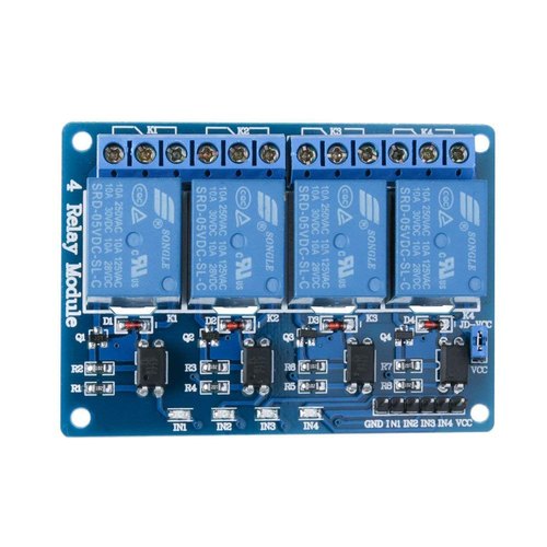
The relay module that I used is active low
All inputs pins are pull up manually by using 4.7k resistor

/*************************************************************
  Download latest Blynk library here:
    https://github.com/blynkkk/blynk-library/releases/latest

  Blynk is a platform with iOS and Android apps to control
  Arduino, Raspberry Pi and the likes over the Internet.
  You can easily build graphic interfaces for all your
  projects by simply dragging and dropping widgets.

    Downloads, docs, tutorials: http://www.blynk.cc
    Sketch generator:           http://examples.blynk.cc
    Blynk community:            http://community.blynk.cc
    Follow us:                  http://www.fb.com/blynkapp
                                http://twitter.com/blynk_app

  Blynk library is licensed under MIT license
  This example code is in public domain.

 *************************************************************
  This example runs directly on ESP8266 chip.

  Note: This requires ESP8266 support package:
    https://github.com/esp8266/Arduino

  Please be sure to select the right ESP8266 module
  in the Tools -> Board menu!

  Change WiFi ssid, pass, and Blynk auth token to run :)
  Feel free to apply it to any other example. It's simple!
 *************************************************************/

/* Comment this out to disable prints and save space */
#define BLYNK_PRINT Serial

#include <ESP8266WiFi.h>
#include <BlynkSimpleEsp8266.h>

// You should get Auth Token in the Blynk App.
// Go to the Project Settings (nut icon).


char auth[] = "13123123";


// Your WiFi credentials.
// Set password to "" for open networks.
char ssid[] = "*******";
char pass[] = "*******";
#define speed_1_out     D1    //Drive the relay one which is controlling  the speed level one of the Fan
#define speed_2_out     D2    //Drive the relay two which is controlling the speed level 2 of the Fan
#define speed_3_out     D4    //Drive the relay three which is controlling the speed level 3 of the Fan

#define mainSwitch      D3    //Drive the relay four which is turning of power to the fan

#define off_switch     D5     //Read the momentary wsitch for off the fan
#define speed_1_switch D6     //Read the momentary wsitch for speed 1
#define speed_2_switch D7     //Read the momentary wsitch for speed 2
#define speed_3_switch D8     //Read the momentary wsitch for speed 3

unsigned char offSwitch;              //veriable to store status read from the " off_switch "
unsigned char speed_1_switch_read;    //veriable to store status read from the " speed_1_switch "
unsigned char speed_2_switch_read;    //veriable to store status read from the " speed_2_switch "
unsigned char speed_3_switch_read;    //veriable to store status read from the " speed_3_switch "

bool x = 1;
long offTime;
int previous = LOW;                             // the previous reading from the input pin
long debounce = 200;                            // the debounce time, increase if the output flickers
long Time = 0;                                  // the last time the output pin was toggled//
long const OnOff_Duration = 5000;
long OnOff_Duration_offset;
void setup() {
  Blynk.begin(auth, ssid, pass);
 // Serial.begin(115200);
  pinMode(speed_1_out , OUTPUT);
  pinMode(speed_2_out , OUTPUT);
  pinMode(speed_3_out , OUTPUT);

  pinMode(mainSwitch , OUTPUT);

  pinMode(off_switch , INPUT);
  pinMode(speed_1_switch , INPUT);
  pinMode(speed_2_switch , INPUT);
  pinMode(speed_3_switch , INPUT);
  digitalWrite(speed_1_switch, HIGH);
  digitalWrite(speed_2_switch, HIGH);
  digitalWrite(speed_3_switch, HIGH);
  digitalWrite(speed_1_out, HIGH);
  digitalWrite(speed_2_out , HIGH);
  digitalWrite(speed_3_out, HIGH);
  digitalWrite(mainSwitch, HIGH);

  //digitalWrite(mainSwitch, HIGH);
  OnOff_Duration_offset = OnOff_Duration;

}

void loop() {

  if ((millis() - offTime) > OnOff_Duration_offset)//150000
  {
    offTime = millis();
    digitalWrite(mainSwitch, x = !x);
    if (digitalRead(speed_1_out) == HIGH && digitalRead(speed_2_out) == HIGH  && digitalRead(speed_3_out) == HIGH ) {
      digitalWrite(mainSwitch, HIGH);
    }

  }

  speed_1_switch_read = digitalRead(speed_1_switch);
  if (speed_1_switch_read == HIGH && previous == LOW && millis() - Time > debounce) {
    digitalWrite(speed_1_out, LOW);
    digitalWrite(speed_2_out, HIGH);
    digitalWrite(speed_3_out, HIGH);
    digitalWrite(mainSwitch, LOW);
    offTime = millis();
    Time = millis();
    x = 1;

  }

  speed_2_switch_read = digitalRead(speed_2_switch);
  if (speed_2_switch_read == HIGH && previous == LOW && millis() - Time > debounce) {
    digitalWrite(speed_1_out, HIGH);
    digitalWrite(speed_2_out, LOW);
    digitalWrite(speed_3_out, HIGH);
    digitalWrite(mainSwitch, LOW);
    offTime = millis();
    Time = millis();
    x = 1;

  }

  speed_3_switch_read = digitalRead(speed_3_switch);
  if (speed_3_switch_read == HIGH && previous == LOW && millis() - Time > debounce) {
    digitalWrite(speed_1_out, HIGH);
    digitalWrite(speed_2_out, HIGH);
    digitalWrite(speed_3_out, LOW);
    digitalWrite(mainSwitch, LOW);
    offTime = millis();
    Time = millis();
    x = 1;

  }

  offSwitch = digitalRead(off_switch);
  if (offSwitch == HIGH && previous == LOW && millis() - Time > debounce) {
    digitalWrite(speed_1_out, HIGH);
    digitalWrite(speed_2_out, HIGH);
    digitalWrite(speed_3_out, HIGH);
    digitalWrite(mainSwitch, HIGH);
    Time = millis();

  }
  Blynk.run();
}

BLYNK_WRITE(V1) { // Widget for interval timing
  //Serial.println(param.asInt());
  switch (param.asInt())//param.asInt()

  {
    case 1: { // Item 1
        digitalWrite(speed_1_out, HIGH);
        digitalWrite(speed_2_out, HIGH);
        digitalWrite(speed_3_out, HIGH);
        digitalWrite(mainSwitch, HIGH);
        break;
      }
    case 2: { // Item 2

        digitalWrite(speed_1_out, LOW);
        digitalWrite(speed_2_out, HIGH);
        digitalWrite(speed_3_out, HIGH);
        digitalWrite(mainSwitch, LOW);
        offTime = millis();
        x = 1;
        break;
      }
    case 3: { // Item 3
        digitalWrite(speed_1_out, HIGH);
        digitalWrite(speed_2_out, LOW);
        digitalWrite(speed_3_out, HIGH);
        digitalWrite(mainSwitch, LOW);
        offTime = millis();
        x = 1;
        break;
      }
    case 4: { // Item 3
        digitalWrite(speed_1_out, HIGH);
        digitalWrite(speed_2_out, HIGH);
        digitalWrite(speed_3_out, LOW);
        digitalWrite(mainSwitch, LOW);
        offTime = millis();
        x = 1;
        break;
      }
  }
}

BLYNK_WRITE(V4) {
  int value = param.asInt();  // This gets the 'value' of the Widget as an integer
  OnOff_Duration_offset = OnOff_Duration * value;
 // Serial.println(OnOff_Duration_offset);


}

following code are used to turn OFF and ON the fan as per the value set to the " OnOff_Duration_offset " veritable . This is used to for the purpose of power saving . the value of variable called " OnOff_Duration_offset " control by the slider module

if ((millis() - offTime) > OnOff_Duration_offset)//150000
  {
    offTime = millis();
    digitalWrite(mainSwitch, x = !x);
    if (digitalRead(speed_1_out) == HIGH && digitalRead(speed_2_out) == HIGH  && digitalRead(speed_3_out) == HIGH ) {
      digitalWrite(mainSwitch, HIGH);
    }

  }

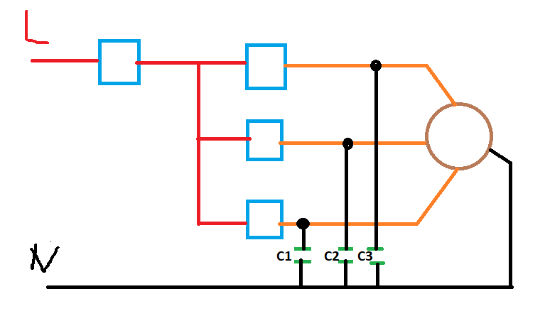
I am using Node MCU ESP8266

Without connecting motor wires everything is working Perfect, Once the motor wires connected to the relay and once AC powered it operate in unpredictably

The first thing you need to do is to sort-out your void loop - itā€™s an absolute mess!
You need to either user a timer to poll your physical switches, or attach interrupts to them and use debounce code.
http://help.blynk.cc/getting-started-library-auth-token-code-examples/blynk-basics/keep-your-void-loop-clean

Secondly, Iā€™d advise you to either switch from using ā€œDā€ pin designations to using GPIO numbers, or at the very least add a note in the comments about which GPIO each pin relates to.

Pulling GPIO15 (D8 - used for speed_3_switch) HIGH with a resistor is a bad move. It has a built-in pull-down resistor and needs to be LOW at startupā€¦

Thirdly, if everything works correctly with no AC load attached to the high voltage side of the relays, but becomes problematic when a load is attached then you are suffering from EMF interference from your load. The only way to solve this is to put a suitably sized and properly rated capacitor across the load terminals to filter out the EMF interference.

TBH, three inputs and four outputs is pushing the limits of what you can achieve with an ESP8266. Youā€™d be better switching to an ESP32 for this type of project, although Iā€™m nit 100% clear why the mainSwitch is required.

Pete.

although Iā€™m nit 100% clear why the mainSwitch is required.

Pete.
[/quote]

mainSwitch is used cut of the power to the fan every three minutes( Or desired time by the user ) Lets suppose switch on the fan by 8.00PM then fan is working all night , but in my method fan stay ON 3 minutes and stay OFF three minutes that mean 50% power save
:rofl:

But thereā€™s nothing to stop you cutting power with the currently selected speed 1, 2 or 3 relays. It has the same effect without the need for the 4th relay.

Pete.

Yes that can reduce the power consumption too , Thanks for idea

But in this case we have to keep saving last speed user selected ,

Yes, but you should be synchronising that to your Blynk segmented switch anyway, so itā€™s easy to pull it back with a Blynk.syncVirtual at the point when your off-timer ends.

Pete.

You mean due to GOIP15 should low during the boot,

Other than this generally for microcontroller external pull upā€™s more stable than the internal pull up ā€¦Am I correct ?

Iā€™ve never had the need to use external pull-ups.
The only reason I would use external resistors would be to pull a pin down (LOW).

Pete.

Hope this will be reduce the EMF interference