I’d put the capacitors as close as possible to the relay connectors, and make sure that they are X capacitors designed to be placed across line and neutral.
Pete.
I’d put the capacitors as close as possible to the relay connectors, and make sure that they are X capacitors designed to be placed across line and neutral.
Pete.
Little improvement has been done and further improvement to be done
/*************************************************************
  Download latest Blynk library here:
    https://github.com/blynkkk/blynk-library/releases/latest

  Blynk is a platform with iOS and Android apps to control
  Arduino, Raspberry Pi and the likes over the Internet.
  You can easily build graphic interfaces for all your
  projects by simply dragging and dropping widgets.

    Downloads, docs, tutorials: http://www.blynk.cc
    Sketch generator:           http://examples.blynk.cc
    Blynk community:            http://community.blynk.cc
    Follow us:                  http://www.fb.com/blynkapp
                                http://twitter.com/blynk_app

  Blynk library is licensed under MIT license
  This example code is in public domain.

 *************************************************************
  This example runs directly on ESP8266 chip.

  Note: This requires ESP8266 support package:
    https://github.com/esp8266/Arduino

  Please be sure to select the right ESP8266 module
  in the Tools -> Board menu!

  Change WiFi ssid, pass, and Blynk auth token to run :)
  Feel free to apply it to any other example. It's simple!
 *************************************************************/

/* Comment this out to disable prints and save space */
#define BLYNK_PRINT Serial

#include <ESP8266WiFi.h>
#include <BlynkSimpleEsp8266.h>

// You should get Auth Token in the Blynk App.
// Go to the Project Settings (nut icon).


char auth[] = "1234555";


// Your WiFi credentials.
// Set password to "" for open networks.
char ssid[] = "******";
char pass[] = "******";
#define speed_1_out     D1    //Drive the relay one which is controlling  the speed level one of the Fan
#define speed_2_out     D2    //Drive the relay two which is controlling the speed level 2 of the Fan
#define speed_3_out     D4    //Drive the relay three which is controlling the speed level 3 of the Fan

#define mainSwitch      D3    //Drive the relay four which is turning of power to the fan

#define off_switch     D5     //Read the momentary wsitch for off the fan
#define speed_1_switch D6     //Read the momentary wsitch for speed 1
#define speed_2_switch D7     //Read the momentary wsitch for speed 2
#define speed_3_switch D8     //Read the momentary wsitch for speed 3

unsigned char offSwitch = 0;              //veriable to store status read from the " off_switch "
unsigned char speed_1_switch_read = 0;    //veriable to store status read from the " speed_1_switch "
unsigned char speed_2_switch_read = 0;    //veriable to store status read from the " speed_2_switch "
unsigned char speed_3_switch_read = 0;    //veriable to store status read from the " speed_3_switch "
unsigned char speed_1_switch_detected = 0;
unsigned char speed_2_switch_detected = 0;
unsigned char speed_3_switch_detected = 0;

bool x = 1;
long offTime = 0;
int previous = LOW;                             // the previous reading from the input pin
long debounce = 200;                            // the debounce time, increase if the output flickers
long Time = 0;                                  // the last time output pin was toggled//
long const OnOff_Duration = 5000;
long OnOff_Duration_offset = 0;
void setup() {
  Blynk.begin(auth, ssid, pass);
  // Serial.begin(115200);
  pinMode(speed_1_out , OUTPUT);
  pinMode(speed_2_out , OUTPUT);
  pinMode(speed_3_out , OUTPUT);

  pinMode(mainSwitch , OUTPUT);

  pinMode(off_switch , INPUT);
  pinMode(speed_1_switch , INPUT);
  pinMode(speed_2_switch , INPUT);
  pinMode(speed_3_switch , INPUT);
  digitalWrite(speed_1_switch, HIGH);
  digitalWrite(speed_2_switch, HIGH);
  digitalWrite(speed_3_switch, HIGH);
  digitalWrite(speed_1_out, HIGH);
  digitalWrite(speed_2_out , HIGH);
  digitalWrite(speed_3_out, HIGH);
  digitalWrite(mainSwitch, HIGH);

  OnOff_Duration_offset = OnOff_Duration;

}

void loop() {
  Blynk.run();
  main_Switch();
}

void main_Switch() {

  if ((millis() - offTime) > OnOff_Duration_offset)//150000
  {
    offTime = millis();
    digitalWrite(mainSwitch, x = !x);
    if (digitalRead(speed_1_out) == HIGH && digitalRead(speed_2_out) == HIGH  && digitalRead(speed_3_out) == HIGH ) {
      digitalWrite(mainSwitch, HIGH);
    }

  }

  read_switch(); //read status of speed selector switch
}

void read_switch() {
  speed_1_switch_read = digitalRead(speed_1_switch);
  if (speed_1_switch_read == HIGH && previous == LOW && millis() - Time > debounce) {
    speed_1_switch_detected = 1;
    speedSwitch('L');
  }

  speed_2_switch_read = digitalRead(speed_2_switch);
  if (speed_2_switch_read == HIGH && previous == LOW && millis() - Time > debounce) {
    speed_2_switch_detected = 1;
    speedSwitch('M');
  }

  speed_3_switch_read = digitalRead(speed_3_switch);
  if (speed_3_switch_read == HIGH && previous == LOW && millis() - Time > debounce) {
    speed_3_switch_detected = 1;
    speedSwitch('N');
  }

  offSwitch = digitalRead(off_switch);
  if (offSwitch == HIGH && previous == LOW && millis() - Time > debounce) {
    speedSwitch('O');

  }


} // End of readSwitch2 function
BLYNK_WRITE(V1) { // Widget for interval timing
  switch (param.asInt())//param.asInt()
  {

    case 1: { // off
        speedSwitch('O');
        break;
      }
    case 2: { // speed 1
        speedSwitch('L');
        break;
      }
    case 3: { // speed2
        speedSwitch('M');
        break;
      }
    case 4: { // speed 3
        speedSwitch('N');
        break;
      }
  }
}

BLYNK_WRITE(V4) {
  int value = param.asInt();  // This gets the 'value' of the Widget as an integer
  OnOff_Duration_offset = OnOff_Duration * value;
}

void speedSwitch(unsigned char Speed) {
  switch (Speed) {
    case 'L': { // speed1
        digitalWrite(speed_1_out, LOW);
        digitalWrite(speed_2_out, HIGH);
        digitalWrite(speed_3_out, HIGH);
        digitalWrite(mainSwitch, LOW);
        offTime = millis();
        Time = millis();
        x = 1;
        break;
      }
    case 'M': { // speed 2
        digitalWrite(speed_1_out, HIGH);
        digitalWrite(speed_2_out, LOW);
        digitalWrite(speed_3_out, HIGH);
        digitalWrite(mainSwitch, LOW);
        offTime = millis();
        Time = millis();
        x = 1;
        break;
      }
    case 'N': { // speed 3
        digitalWrite(speed_1_out, HIGH);
        digitalWrite(speed_2_out, HIGH);
        digitalWrite(speed_3_out, LOW);
        digitalWrite(mainSwitch, LOW);
        offTime = millis();
        Time = millis();
        x = 1;
        break;
      }
    case 'O': { // off
        digitalWrite(speed_1_out, HIGH);
        digitalWrite(speed_2_out, HIGH);
        digitalWrite(speed_3_out, HIGH);
        digitalWrite(mainSwitch, HIGH);
        Time = millis();
        break;
      }
  }
}
Doesn’t look like it will work to me.
Pete.
What do you think about RC Snubber cct to reduce EMF
A capacitor worked perfectly for me when I had a similar problem.
Pete.
I replaced the 4 capacitors across the AC line . Now everything is working perfectly. Thanks for your grate support
Now I have to improve the code and change to the ESP32
Thanks one again
My Fan is still working no error
Hoped you are doing well
Suddenly my system stop . Can not understand the reason
I believe that Auth Token has been changed some how .
Your serial monitor will give an “Invalid Auth Token” message if that is the case.
Pete.
Was this project a success? If so, can you put the circuit diagram and code?
Yes it is working successfully
Please follow the thread it has everything,
If you need any additional info please post here
Sorry for late reply
Thanks
Yes This is good for celling fan
Why not for pedestal fan instead of relay ? ![]()
The pedestal fan what I am using comes with three winding for speed control but Celling fan just two wire . What do you think
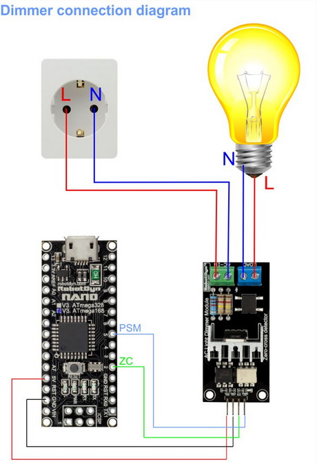
I think you have to push the fast speed button level 3 and use the module as a AC dimmer at the input AC
Yes ,… That is good idea but I don’t have experience working with that way
Does it working
In this case we have to remove the latching selector switches which originally comes with right ?
How do we manage manual control and app slider control