It’s nothing spectacular or groundbreaking. It’s yet another ESP8266 (12F) reading a DS18B20 temperature sensor. But, I figured I’d post in case someone finds it useful.
Some details
Most settings are #defined at the top of the sketch, so it’s easy to “tweak” them. I’ll put the values I’m using in parentheses ().
A #define is used to select Celsius or Fahrenheit.
Temperature is read and reported at a fixed interval (30 seconds).
The sketch will alert if the temperature goes to low or too high. The low and high temperature points are set by app widgets (pins V2 and V3). (I use the step control widget but a slider, or anything that can send an integer value to a virtual pin, could be used). To alert, the sketch will send a push notification and also change the color of the widget that displays the temperature to (blue) for low or (red) for high. The widget color will be changed to (green) when the temperature returns to within the normal range
Blynk.syncAll() is used to keep the alert values in sync between the app and the device whenever the device connects to the server, in case the values are changed while the device isn’t connected.
A hysteresis value (3 degrees) is added to the low and high alert values to prevent frequent multiple alerts if the temperature fluctuates around the low or high set point.
An LED (the ESP8266’s on board blue LED) is used to indicate status:
A very brief flash (30mS) each time the temperature is read successfully (every 30 seconds).
A long flash (5 seconds) if the temperature read is not successful.
Rapid blinking (200mS every 500mS) if the sensor isn’t detected when the sketch starts up.
A long flash (2 seconds) if the connection goes down. This flash occurs each time Blynk tries to reconnect but is unsuccessful, which is about every 9 or 10 seconds.
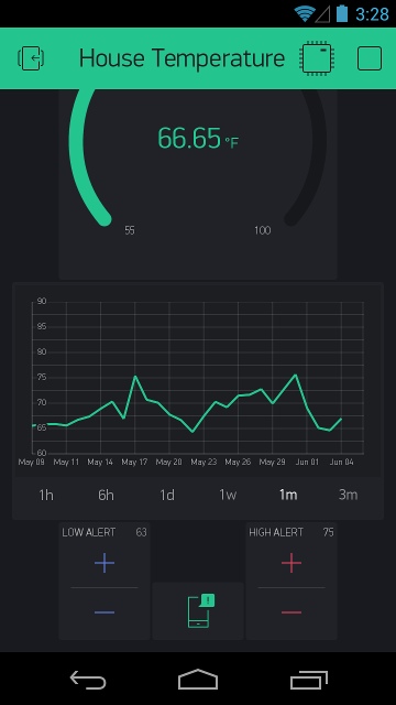
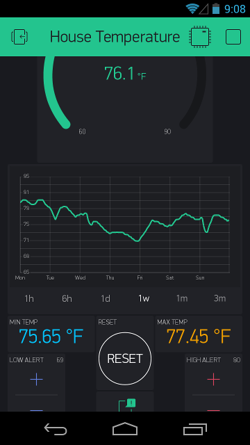
The temperature is sent on two virtual pins (V0 and V1). The same value is sent on both pins but one (V0) also sends widget color changes for low and high alerts. I use a gauge for (V0) and a history graph for (V1).
The sketch is well behaved in terms of Blynk guidelines. Timers are used to control sketch operation. Even the required “wait for sensor temperature conversion” (800mS) is handled by a timer, instead of a delay, which I haven’t seen any other DS18B20 Blynk sketch do. There are some delays used but only for status LED timing in places that won’t affect the proper operation of the Blynk library.
UPDATE: I’ve added tracking and display of the minimum and maximum temperatures and the ability to reset these. See my later post in this topic for a screen shot.
The minimum and maximum temperatures reached are sent on virtual pins (V4 for min, V5 for max) whenever they change. A virtual pin (V6 ), which receives a boolean value, is used to reset these. I used labeled value widgets for displaying and a momentary button for resetting.
My app layout
This screen shot is scrolled down. When scrolled up, the gauge is fully displayed and the step control and notification widgets are off the bottom and not visible, at least on my phone.
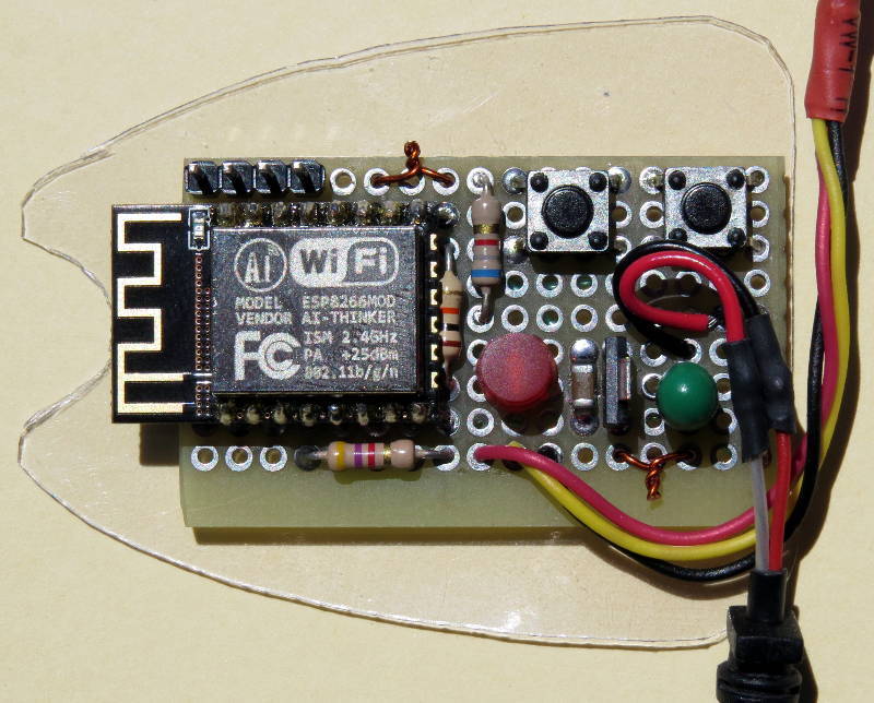
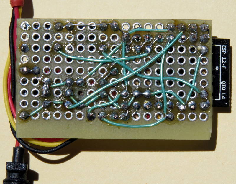
I used a bare ESP8266-12-F module. I mounted and wired it on a piece of prototype board along with a 3.3V regulator, reset and program buttons, and the necessary resistors and capacitors. The red LED just indicates 3.3V power.
Power comes from a 5V charger supply for an old Samsung cell phone (with the connector removed and the wires hard wired to the circuit board).
The DS18B20 is wired to the end of a short length of solid core wires so it can be positioned away from the heat generated by the circuit board.
The case is from a (used) pack of dental floss, with Velcro used to hold it more securely closed.
@dananmo, It’s just an ESP8266 wired as standard, with a DS18B20 attached to one of the pins (I used pin 4). However, the code is generic for Blynk, and the OneWire and DallasTemperature libraries support all architectures, so it should work on anything supported by Blynk just by replacing the #includes for ESP8266WiFi.h and BlynkSimpleEsp8266.h and setting #define ONEWIRE_PIN to the pin you use for the DS18B20.
Since I used a 5V adapter for power, I also added a 3.3V LDO regulator (an AP2114H).
I can create a schematic of my exact circuit, if you wish, but it may take a while before I can find the time to do it.
@MLXXXp, as you said: not groundbreaking, but it is nicely done - even the circuit and also the case, i like the idea! plus very organised documentation. good job!
maybe in the next version you can get rid of the psu, and use 1-2 lithium batteries 18650 and a small charger module with micro usb port. if you set the esp to deep sleep, and reduce the measure interval to 5 minutes, you probably could fix the sensor directly outside of the case, because no heat will be produced by the esp.
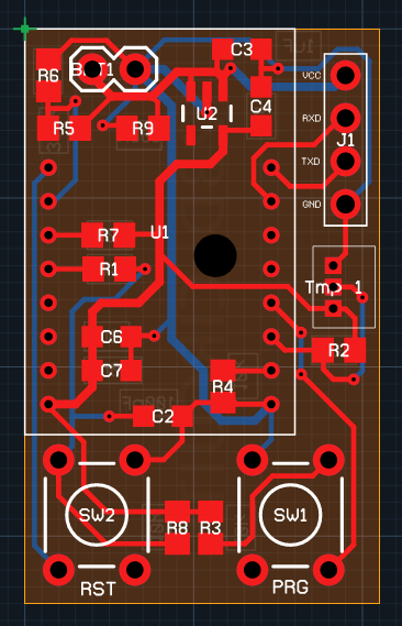
The simplicity was inspiring so I made a pcb, not realising until afterwards that your own design
governed the placement of my components somewhat
It’s ordered and I hope I didnt miss anything
For my purposes, I have no problem powering from the mains. And, I didn’t want to deal with having to charge and maintain batteries.
However, putting an ESP into deep sleep with Blynk has been discussed elsewhere in this forum, and adding that capability to my code base shouldn’t be too difficult.
I took a quick glance at it but haven’t verified it fully. It doesn’t exactly match mine but looks mostly correct.
I used GPIO4 for the sensor. It looks like you’re using GPIO2 (so remember to change the #define ONEWIRE_PIN in the code).
I see you’re using the ADC to monitor the input voltage.
Since my power is regulated 5V, I put a 1N4001 diode between the 5V adapter output and Vin of the regulator. This splits the power dissipation between the diode and the regulator. It also allows me to power the board from 5V placed on the Vin pin of the programming header (which is connected to Vin of the regulator) without worrying about feeding voltage into the adapter (since the adapter is hard wired and can’t be disconnected).
For an ESP8266-12, GPIO2 is connected to the on board LED, so you’re going to have a conflict. If you want to have the LED status indication that’s in my code, you’ll have to use an external LED on a different pin, or move the sensor to a different pin.
I just wanted to say thanks for posting this - I’ve had Blynk, an ESP12e and a ds18b20 sitting around for a couple years wanting to do this exact thing…but never had the time to work on it. Now I’m up and running! I’m going to use this for making some freezer temp monitors. Thanks for sharing!
@Mauricio_Lima, Are you asking about the hardware or the software?
For the hardware, additional sensors can be added in parallel on the same wire. (That’s why the interface is called “1-Wire”.)
For the software, the startSensorRead() function already starts the conversion for all sensors connected to the bus, so no changes are required there.
You would have to expand and modify the sensorRead() function to read all the sensors, instead of just one, and add virtual pins for them. If you put the sensor device addresses in an array, you could use a loop and index to read them.
The initialisation for more than one sensor will have to be performed in setup(), as well. Essentially, anywhere where the tempSensor variable containing the device address is used.
What you have to consider is how to handle monitoring, alerts and errors for more than one sensor. Do you want separate maximum and minimum temperature tracking, and max/min alerts and notifications, for each sensor? What happens when one or more sensors fail but the others remain working, in terms of flashing the LED for status indication?
Very nice and complete presentation of your project!
Since I’m a self proclaimed DS18B20 wrangler I have some input that might speed things up, even if not necessary
// The number of bits of temperature resolution
// 9 = 0.5, 10 = 0.25, 11 = 0.125, 12 = 0.0625 degrees Celsius
#define TEMPERATURE_RES_BITS 10

// Temperature conversion wait time, in milliseconds
#define READ_CONV_WAIT 800

// We'll do the "wait for conversion" ourselves using a timer,
// to avoid the call to delay() that the library would use
sensors.setWaitForConversion(false);
The conversation time with 10 bit resolution is only 187.5 ms, so no need to wait for 800 ms. You don’t even have to wait for the 187.5 ms if you don’t want to. You could execute other code and come back after ~200 ms and just read the result of the conversation, which only takes about 30 ms.
I’m using two timers in my project to do this “hit-n-run” on the sensors
@Mauricio_Lima There is examples of how to use multiple sensors hidden somewhere in the forum. I can’t remember where so you have to search for your self


 Can you share the blynk project also? Thanks.