It’s fine to post your code here, just so long as you use triple backticks correctly.
It would probably be best if you described your hardware and app setup in sufficient detail to allow others to replicate your setup, or at least understand your configuration without having to ask dozens of questions.
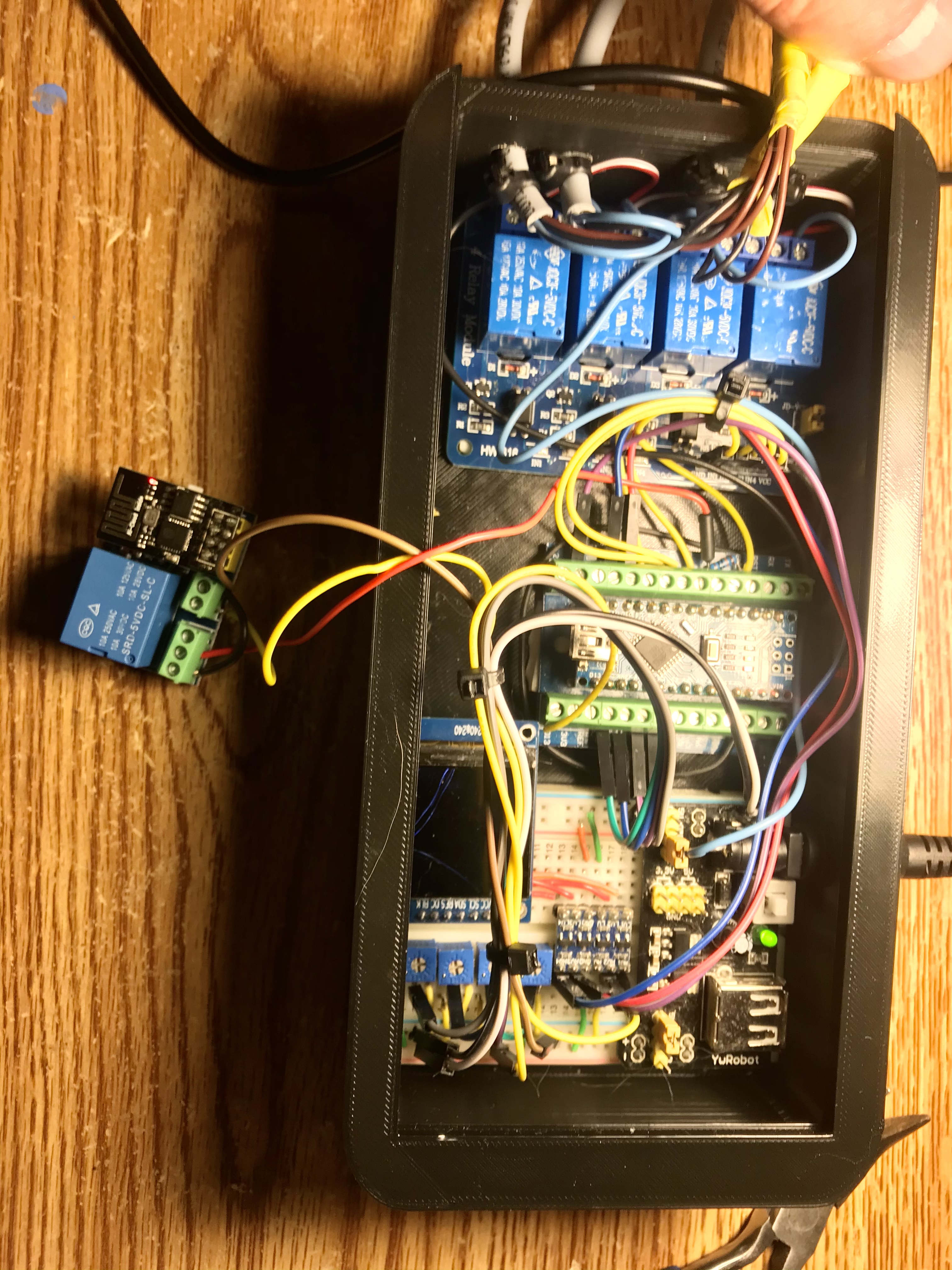
Here is a short version of the project I’m doing.
I have four relay on one board that controls four pumps that is controlled by an arduino nano to water four different plants. Over time ive added four potentiometers to control the time that the pumps stay on because some plants didn’t need as much water as others. I mounted those pots on a breadboard and added an lcd to show the timers preset.on the breadboard I also mounted a breadboard power supply to supply the two voltages I needed for the setup. I printed a box to fit all the parts. If something like this is of you interest I’ll supply the sketch. One other thing is I’m using an esp01 with a relay to be the trigger for the event.
I hope that this is enough information for you to understand the scope of work. Have a great day. Thanks to blynk for the space.
Hello friend @jmartens2 , it’s great, in my case the only thing I need is that the esp01 with its relay, activate the irrigation at my will. I do not need arduino, I simply need the esp01 relay to activate the irrigation pump relay for a certain time and after that time it only cuts off. Thank you very much, if you could put the esp01 code to see it and make modifications and tests, I would appreciate it. a greeting.
/*************************************************************
  Download latest Blynk library here:
    https://github.com/blynkkk/blynk-library/releases/latest

  Blynk is a platform with iOS and Android apps to control
  Arduino, Raspberry Pi and the likes over the Internet.
  You can easily build graphic interfaces for all your
  projects by simply dragging and dropping widgets.

    Downloads, docs, tutorials: http://www.blynk.cc
    Sketch generator:           http://examples.blynk.cc
    Blynk community:            http://community.blynk.cc
    Follow us:                  http://www.fb.com/blynkapp
                                http://twitter.com/blynk_app

  Blynk library is licensed under MIT license
  This example code is in public domain.

 *************************************************************
  This example runs directly on ESP8266 chip.

  Note: This requires ESP8266 support package:
    https://github.com/esp8266/Arduino

  Please be sure to select the right ESP8266 module
  in the Tools -> Board menu!

  Change WiFi ssid, pass, and Blynk auth token to run :)
  Feel free to apply it to any other example. It's simple!
 *************************************************************/

/* Comment this out to disable prints and save space */
#define BLYNK_PRINT Serial


#include <ESP8266WiFi.h>
#include <BlynkSimpleEsp8266.h>

// You should get Auth Token in the Blynk App.
// Go to the Project Settings (nut icon).
char auth[] = "your authorization code";

/*// This function will run every time Blynk connection is established
  BLYNK_CONNECTED() {
  // Request Blynk server to re-send latest values for all pins
  Blynk.syncAll();
  }
*/
  // Your WiFi credentials.
  // Set password to "" for open networks.
  char ssid[] = "your ssid";
  char pass[] = "your password";


  void setup()
  {
    // Debug console
    Serial.begin(9600);
    pinMode(0,OUTPUT);
    digitalWrite(0,HIGH);
    Blynk.begin(auth, ssid, pass);

  }

   void loop()
  {
    Blynk.run();

  }
Is your relay energized with an output low or high?
Whether it does nor not I recommend using a 555 timer to install a delay to your relay power line. This way the ESP01 can go through its boot process before the relay power becomes available. The 555 timer circuit is simple and that’s what I have done to get around the problem you describe.
In my application I use a 8 second delay upon power up before power becomes available to the relays. It works great and its a simple circuit.
I use a great many devices which contain relays that are controlled by ESP8266s and adding additional circuitry of this type is totally unnecessary.
In fact, in many off the shelf devices such as Sonoff and Shelly smart switches it’s impractical to add additional hardware.
Using a pinMode statement and a corresponding digitalWrite early in the void setup is all that is needed - provided that you (or the 3rd party manufacturer) chooses appropriate pins to connect to the ESP8266.
If the ESP8266 doesn’t have sufficient suitable pins to support your custom built device then using a port expander or an ESP32 is the more appropriate course of action in my opinion.
He says he’s using an ESP01. Are you aware that the ESP01 only has 4 I/O pins? In addition it initiates serial data on at least the TX pin during power up for debug purposes that can’t be eliminated. If TX is used as an output to a relay, the relay it will be energized and de-energized several times.
If you have a better work around please share it because I may want to use it in future projects. I will anxiously look forward to your response because I am currently working on another project with the ESP01.
Again this is very exciting , even though the 555 timer works extremely well in my applications to delay power to the relays until ESP01 power up is complete it would be nice to remove it and make life a little simpler.
Yes, I’m fully aware that only four GPIOs are broken-out on an ESP-01 board.
The Tx pin is LOW for around 50ms at start-up and then it depends what you do with it after that. But, it falls into the category of “not recommended as a GPIO pin” in the table below…
and is therefore unsuitable for driving a relay, which is why I said…
In my opinion, the ESP-01 is really only useful as a WiFi modem for a non IoT enabled device, or to use in a project where physical space is at an absolute premium. However, in this scenario you probably wouldn’t have space for the 555s or relays. My go-to board is the Wemos D1 Mini, or D1 Mini Pro if an external antenna is needed. These boards are significantly smaller than the NodeMCU without the loss of any useable GOIOs.
If you want to stick with ESP8288’s then a port expander such as the MCP23017 is one option. I’ve never tried using one of these with an ESO-01, but in theory it’s possible but I prefer to use them with a D1 Mini…
I read your post on that MCP23017 IO Expansion Board looks interesting; I may have to try it sometime. I have used numerous boards in the past where I felt IO limited so this may be a solution. I would like to try one of those mini’s and will definitely pick up some in the future but I still use the ESP01 when I can; at a dollar a piece they are hard to beat for small projects.
Compared to the outlandish $2.50 for a D1 Mini?
Sometimes it pays to go that extra mile!
TBH, the biggest issue I have with the ESP-01 (other than the limited number of broken-out GPIOs) is that fact that they are so awkward to work with compared to a D1 Mini. The lack of a USB port for debugging is a pain, and although you can stick the ESP-01 onto a USB adapter it’s far less convenient in my opinion.
The thing I love about the D1 Mini is the range of accessories that can be stacked on top, or alongside the main board. I use the double and triple bases quite a bit, along with the prototyping shields, and it’s very convenient to work with and even use as a final solution like the gate release setup shown in this topic…
Hi people. I was looking for some info and came back across this. I would really like to thank Pete knight and bill Donnelly for patience several years ago!
Hi,
I’ve read a lot about this, and since this thread is exactly my question, I’m seeking guidance here.
I’m building a small project to control a garage door. To this end, I’m using a ESP8266 nodemcu, connected to a 4 module relay, and I’m having this exact same problem! Everytime the power goes down, or the ESP8266 reboots, it turns on the relays for a second. I’ve tried to sync with the last value, which is always 0, and also tried to force it to be HIGH on the void setup. Both things didin’t work. Could someone kindly give me some guidance?
Thank you
Tiago Silva
Hi @Blynk_Coeur ,
Thank you for the fast reply.
I did search before, and from my understanding I’m using safe pins. I’m currently using D1 and D2, which correspond to GPIO5 and GPIO4.
I’m new to this and might have miss understood something, if so, please tell me the correct pints to use.
Thank you,
Tiago Silva