I would like to program my Nodemcu esp8266 for my 211 gallons tank via Blynk so that a float is connected and a buzzer when the float is triggered sounds a beep on the buzzer and an alarm mail is sent.
since i do not have my aquarium computer yet and should my return pump fail, my sump runs over in a few hours and so i can send someone to my apartment to see to the right I need this info and should happen at night I will be woken up by the buzzer.
thanks for any help
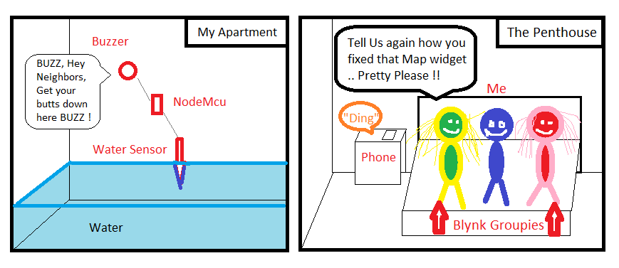
Blynk groupies 
2 Likes
This is what I need!
But I don’t can find any sketch online about this.
Yes I want to need mail ore notifications
Honestly, you are making your end result more complex (at the moment) by using blynk.
The email feature is just a small addon to the full features of the blynk application. Its kinda like getting a new Windows 10 machine and only using the calculator application.
Have you searched for “nodemcu sending email” ?
However, after you get it up and running, come back to Blynk to see about monitoring and controls from the phone. Thats where it shines.
yes I had! nothing useful in connection with a float. I would also have a sketch long I can configure and then it comes to the fact that I do not know how to connect the float should or integrate. I would be completely long when the float triggers the buzzer starts and a mail is sent! it does not necessarily have to run over blynk.
A float is just a switch, which closes when the water reaches a certain level. You won’t have any problems finding sketches - either with or without Blynk integration - that uses a physical switch to trigger an action.
Pete.
only how does the connection schematic look to! and how do you program something !? because I do not know how to turn on a switch that has two connections. how to attach it to a pump is clearly not if the floating switch should work alone
Your float switch would be connected to one of your digital pins on your NodeMCU with the other side of the switch connected to either the ground or 3.3v pin (depending on which digital pin you use, and how you choose to work).
You’d previously said that you wanted to sound a buzzer and send an alert, but now you’re talking about wanting to activate a pump as well (or maybe instead- I can’t tell).
The pump will need a relay attached to a different digital pin on your NodeMCU. Your code will activate your pump via the digital pin and relay when the float switch closes.
Without a second float switch to know when the water level is down to your minimum setting, you’ll need to run your pump for a preset duration so that it empties sufficient water without running dry.
If you want a high power buzzer then that will probably require a relay too.
This forum isn’t about teaching basic electronics, or basic coding, you’ll need to figure that out for yourself. We’ll help if you’re struggling with the Blynk side of things once you have your wiring sorted and some code that operates correctly without the Blynk integration in place.
It will be a steep learning curve, but the rewards will be worth it - because you too will be able to have your own Blynk groupies 
Pete.
this answer is great! No, again, I just want a float switch and a buzzer in action. When closing the switch, the buzzer should go off and it should be sent a mail. not more! So I have to connect the float with +3.3 volt and a digital connection !? then the buzzer with +/- 3.3 volts and a digital pin. But what does the programming look like? I’ve been searching the internet for a long time but never found both in combination. I know that you need a relay for a pump. The pump is only controlled when my aquarium controller was delivered. until then I need this circuit to have a little bit of security.
// I found this code but not connected to blynk and to much settings
i only need buzzer alert if float switch is on and send me an e-mail when alert.
is float switch off nothing should happens
/*****************************************************************************
 *
 * Author: Obushenkov Alexey Andreevich
 * Group in VK https://vk.com/engineer24
 * YouTube channel https://www.youtube.com/channel/UCih0Gcl9IEdkR8deDJCiodg
 * Inzhenerki Engineering room
 *
 *****************************************************************************
 * A sketch is assembled on site http://docs.blynk.cc/
 *****************************************************************************
 * Modules in the project
 * ESP8266 NodeMCU Lua WIFI V3 (3,75 $) https://goo.gl/GFDYq0
 * NodeMCU L293D Motor Shield Board for ESP-12E (1.68 $) https://goo.gl/T0WwT6
 * Infrared PIR motion sensor HC - SR501 (0,95 $) https://goo.gl/0mCfOL
 * 1-channel relay control the High and Low levels (0,99 $) https://goo.gl/SnFuXY
 * Passive Buzzer the Buzzer (0,50 $) https://goo.gl/clKuKb
 *
 *****************************************************************************
 * What is the essence of the sketch
 * Simplest alarm
 * Triggered by the Infrared motion sensor PIR sensor (HC SR501) is in security mode
 * Blink sends notifications to a Mobile device as a PUSH notification and an email
 * plus relay to activate anything.
 * Takes the protection of just using the widget Button mode SWITCH she is disarmed.
 * That we would know under protection or not PIN D4 (sedit LED) under protection will glow,
 * Without protection will be off.
 * Depending on the condition of the system, changing its appearance
 * sent messages, etc.
 *
 *****************************************************************************
 * V1 - Widget LED (Color led) (although in my case, it is not particularly needed)
 * V2 - Widget BUTTON (the Button arm and disarm of the alarm)
 * V10 - Widget Value Display or Labeled Value (a Reflection of the status of the system)
 * V11 - Widget Value Display or Labeled Value (the Reflection from the thermometer)
 *
 * also nugene widgets (they can be unused, but need to remember to disable it in the code
 * otherwise, for stability do not meet)
 * RTC real time Clock
 *
 * Notification - notification Pushup
 * Mail - E-Mail
 * Twitter - Twitter
 *****************************************************************************
 *
 */

// If sousie line raskomentiruyte performance drops to 10 TIMES!!!
// After debugging the project to zakommentirovat
// #define BLYNK_PRINT Serial
// #define BLYNK_DEBUG

// By default, the Maximum allowed email + subject + message length is 120 characters.
// However, you can increase this limit if needed.
// ESP for example, you can set it to 1200 (don't know how it will affect performance)
// By the way Russian characters guzzle two times more than English
#define BLYNK_MAX_SENDBYTES 600

// Library ESP and Blynk
#include <ESP8266WiFi.h>
#include <BlynkSimpleEsp8266.h>

// Library for firmware ESP by air
#include <ESP8266mDNS.h>
#include <WiFiUdp.h>
#include <ArduinoOTA.h>

// Library for real-time clock
#include <TimeLib.h>
#include <WidgetRTC.h>

// Assignable inputs and outputs
#define PIR D2 // gpio 5 here plug-in infrared sensor
#define LED D4 // gpio 2 here can connect the led, but on the Board he already has (But it's inverted)

// D8 = gpio 15 here we catch relay which is driven by a high level
// if you have a relay with it's low clings through NPN transistor
// for example like this http://amperka.ru/product/bipolar-transistor
//#define RELAY D8 // D8 = gpio 15

#define BUZZER D7 // D7 = gpio 13 here we catch the Squeaker

// color for LEDs and the color of the letters
#define BLYNK_GREEN "#23C48E"
#define BLYNK_BLUE "#04C0F8"
#define BLYNK_YELLOW "#ED9D00"
#define BLYNK_RED "#D3435C"
#define BLYNK_DARK_BLUE "#5F7CD8"
#define BLYNK_WHITE "#FFFFFF"


// Area identity ;-P
// You should get the Auth Token in the Blynk App.
// Go to the Project Settings (nut icon).
char auth[] = "auth";

// Your WiFi credentials.
// Set password to "" for open networks.
char ssid[] = "ssid";
char pass[] = "pass";

char Mail[] = "web@gordonx.de"; // Your e-mail
String Subject = "Subject: Schwimmer Alarm System "; // subject of email

WidgetRTC rtc; // initialize widget real time clock

BlynkTimer timer; // initialize the timer
int timerSpeak_ID; // initialize a variable to hold the timer ID Tweeters
int timerPIRSensor_ID; // initialize a variable to hold the timer ID of the motion Sensor

WidgetLED led1(V1); // registreren widget LED

bool isFirstConnect = true; // Variable for storing state of the first time whether the established connection

bool pirState = false; // initialize variable to store the status Srabatyvaet alarm motion sensor

// initialize variable to store the Alarm condition
// false / off
// true included
bool flagProtection = false;
bool intruderState = LOW; // Variable that stores the triggering of the alarm
int securityStateX = 0; // number of the alarm condition

float B; // initialize variable to store data plavusa point sensor option 2

//************************************************************************************//
// Here starts the code of the program                            //
//************************************************************************************//

BLYNK_CONNECTED()// If has installed the first time, sinhroniziruete all widgets
{
  if (isFirstConnect) {
    Blynk.syncAll(); // syngenesiae all widgets

    // Make string with time and date and dobavlaet to the message
    String currentTime = String(hour()) + ":" + minute() + ":" + second();
    String currentDate = String(day()) + "/" + month() + "/" + year() + " ";

    String Notif = "Hardware Running" + currentDate + "" + currentTime;

    Blynk.notify(Notif);

    //I think the extra sending mail on startup
    //Blynk.email(Mail, Subject, Notif); // my sketch to send better this way
    //Blynk.email("sib.eng24@gmail.com", "Subject: Security ESP ", "Hardware Running"); // standard sending on soap
    isFirstConnect = false;

  }
}

void readPIRSensor() // function to read motion sensor
{
  static int pir = LOW; // declare variable to store
                        // information about the state of digital input PIR
 /*The static keyword is used to create a variable,
  *which is visible to only one function. However, unlike local variables,
  *which are created and destroyed with each function call,
  *static variables remain after the function call, preserving their values between calls.
 */

  if (flagProtection == true && pirState == LOW) // If alarm enabled
  {pir = digitalRead(PIR);} // read the value from a digital input
                              // we are not interested in the state of the sensor while
                              // protection not included
  if (flagProtection == true && pir == HIGH && pirState == LOW) // If alarm is Enabled (ON) and Motion Sensor is triggered
  {pirState = HIGH; // This flag can be reset only by disabling the alarm
   digitalWrite(LED, !pirState); // turn on the led on the Board
  }

  if (flagProtection == false && pirState == HIGH) // If alarm is Off (OFF) and Blile drawdown
  {pirState = LOW; // Reset the flag
   digitalWrite(LED, !pirState); // turn off led
  }

// I'm trying to write this function so that it once again nothing happened

} //readPIRSensor


BLYNK_WRITE(V2) // Read the state of the button (Widget Button) and save the value in flagProtection
{
  flagProtection = param.asInt(); // Read the button state

   if (flagProtection) // if flag is raised
  {timer.enable(timerPIRSensor_ID);} // Enable the timer function readPIRSensor
  else // otherwise
  {timer.disable(timerPIRSensor_ID); // Disable timer function readPIRSensor
  timer.setTimeout(50, readPIRSensor);} // Pull the Motion Sensor function
                                           // once with a delay of 50 Millisecond

}

void messeg() // function for sending messages, depending on the status of the Alarm (securityState)
{
  String Notif; // Variable for storing messages

  // The Respondent RTC and make a string to send
  String currentTime = String(hour()) + ":" + minute() + ":" + second();
  String currentDate = String(day()) + "/" + month() + "/" + year() + " ";

 // depending on the condition of alarm select the desired text
 // and add the date and time
 switch (securityStateX) {
 case 1:
    Notif = "a Strange OBJECT" + currentDate + "" + currentTime;
    break;
 case 2:
    Notif = "Protected" + currentDate + "" + currentTime;
    break;
 case 3:
    Notif = "disarmed after obnoruzheniya OFFENDER" + currentDate + "" + currentTime;
    break;
 case 4:
    Notif = "disarmed" + currentDate + "" + currentTime;
    break;

 //default:
    // code to execute
  }

 static int i = 1; // variable and structure of if else needed for
                   // serial send delay

 // there is a message to be sent
 // you can just zakommentirovat
 // not the desired method of communication
 if (i == 3) {Blynk.notify(Notif); i=1;
 }

 else if (i == 2) {Blynk.email(Mail, Subject, Notif); i++;
 }

 else if (i == 1) {Blynk.tweet(Notif); i++;
 }

}

// Custom widgets (change colors displaying a message), depending on the status of the Alarm (securityState)
void Setting (String color, String Text)
{
 // variable and the design of the if else is needed to
 // serial send delay
 static int i = 1;

 if (i == 4) {led1.setColor(color); i=1;} // Change color LED V1

 else if (i == 3) {Blynk.setProperty(V10, "color", color); i++;}// Change the color of the widget V10

 else if (i == 2) {Blynk.setProperty(V2, "color", color); i++;}// Change the color of the widget V2

 else if (i == 1) {Blynk.virtualWrite(V10, Text); i++;} // Print a message Value Display

}

void sendSetting() // Send settings, depending on the status of the Alarm (securityState)
{

  String Notif; // Variable for storing messages
  String color; // Variable to store color

  // then choose a setting depending on the system state
 switch (securityStateX) {
 case 1:
    Notif = "a Stranger on the OBJECT";
    color = BLYNK_RED;
    break;
 case 2:
    Notif = "Protected";
    color = BLYNK_GREEN;
    break;
 case 3:
    Notif = "disarmed was the Offender";
    color = BLYNK_BLUE;
    break;
 case 4:
    Notif = "disarmed";
    color = BLYNK_BLUE;
    break;

 //default:
    // code to execute
  }

  // call the function Setting and substitute the data
  Setting(color, Notif); // Custom widgets (change colors displaying a message)
}

void securityState () // Define the Alarm status and the corresponding actions produce
{

// State 1 // "If the system is armed" and "sensor Tripped" and "Not Able 1"
// Code executed once
    if (flagProtection == true && pirState == true && securityStateX != 1)
  {
      securityStateX=1; // number of the status of the alarm 1
      intruderState = HIGH;// the Alarm went off

      timer.setTimer(1000, messeg, 3); // call funkciu messeg 3 times, with an interval of 1 second

//      digitalWrite(RELAY, intruderState); // relay

      timer.setTimer(200, sendSetting, 4); // call funkciu sendSetting 4 times, with an interval of 0.2 seconds

      timer.enable(timerSpeak_ID); // Enable the timer function Speak Squeaker


  } // State 1 //

// State 2 // "If the system is armed" and "Sensor is Tripped" and "Not in Condition 2"
// Code executed once
  else if (flagProtection == true && pirState == false && securityStateX != 2)
  {
      securityStateX=2; // Number of alarm condition 2

      timer.setTimer(1000, messeg, 3); // call funkciu messeg 3 times, with an interval of 1 second

      timer.setTimer(200, sendSetting, 4); // call funkciu sendSetting 4 times, with an interval of 0.2 seconds

      timer.disable(timerSpeak_ID); // Disable timer function Speak Squeaker


  } // State 2 //

// Condition 3 // "If security is turned Off" and "Alarm" and "Condition 3"
// Code executed once
  else if (flagProtection == false && intruderState == HIGH && securityStateX != 3)
  {
      securityStateX=3; // number of the status alarm 3
      intruderState = LOW; // Reset the flag triggering the Alarm

      timer.setTimer(1000, messeg, 3); // call funkciu messeg 3 times, with an interval of 1 second

//      digitalWrite(RELAY, intruderState); // turn Off relay

      timer.setTimer(200, sendSetting, 4); // call funkciu sendSetting 4 times, with an interval of 0.2 seconds

      timer.disable(timerSpeak_ID); // Disable timer function Speak Squeaker

   } // State 3 //

// State 4 // "If security is Disabled" and "No Alarm" and "Status 4"
// Code executed once
   else if (flagProtection == false && intruderState == LOW && securityStateX != 4)
   {
    if (securityStateX !=3) // if previous state is not equal to 3 then
    {securityStateX=4; // Number of alarm condition 4

    timer.setTimer(1000, messeg, 3); // call funkciu messeg 3 times, with an interval of 1 second

    timer.setTimer(200, sendSetting, 4); // call funkciu sendSetting 4 times, with an interval of 0.2 seconds

    timer.disable(timerSpeak_ID); // Disable timer function Speak Squeaker

    }

  } // State 4 //

} //securityState


void Speak() // Function for Buzzer Buzzer (Chants)
{
  // Set frequency and duration for the tweeters
tone(BUZZER, 3500, 3500);
} // Speak

//**Start*******************the Send data option 1******************
// Sending data to Blynk. In the Widget settings
// find REDIN RATE and set PUSH. !!!!Only!!!!PUSH!!!!
// otherwise will depart from online

void readSensorB() // function to read sensor B
{

//*********The code for getting random values*******************
//**************************Beginning********************************
  static int x = random (100, 200);
  static int i = 2000;
  if (i > -1) {
    i = i + x;
    B=(float)i/100;
    if (i >= 4000) x = -random (100, 200); // switching control to the maximum
    if (i <= 2000) x = random (100, 200); // switching control to the maximum
    }
//*********The code for getting random values*******************
//**************************End*********************************

//**************************The send data option 1******************
// Sending data to Blynk in the Widget settings
// find REDIN RATE and set PUSH. !!!!Only!!!!PUSH!!!!
// otherwise will depart from online
  Blynk.virtualWrite(V11, B);

//***Depending on the sensor you can change the color and the inscription***
  //Serial.println(B); // print values to serial monitor
  static int hotState = 0;
  if (B > 32 && hotState != 1)
  {hotState = 1;
   Blynk.setProperty(V11, "label", "OPASNOSTI OVERHEAT");// Change the name of the widget V11 (understands only English)
   Blynk.setProperty(V11, "color", BLYNK_RED); // Change the color of the widget V11 red
  }
  else if (B <= 32 && hotState != 2)
  {hotState = 2;
   Blynk.setProperty(V11, "label", "Temperature NORMAL"); // Change the name of the widget V11 (understands only English)
   Blynk.setProperty(V11, "color", BLYNK_WHITE); // Change the color of the widget V11 on white
  }
}
//The bottom line is that in this case we obnavljam data with the frequency which was prescribed
//timer B. This line is
//void setup()
//timer.setInterval(1000L, readSensorB);
//ie update data in the widget manages Our iron (ESP8266)
//**End********************the Send data option 1******************


void reconnectBlynk() // function which checks the connection
{
  if (!Blynk.connected()) { //if there is no connection then
    if (Blynk.connect()) { // conectica
      BLYNK_LOG("Reconnected"); // print in log

    } else {
      BLYNK_LOG("Not reconnected"); // print in log
    }
  }

} // reconnectBlynk

void setup()
{

// Debug console
  Serial.begin(19200);
  Serial.println(" ");
  Serial.println("Launch");

// Custom inputs and outputs
  pinMode (LED,OUTPUT);
  digitalWrite(LED, HIGH);
//  pinMode (RELAY,OUTPUT);
  pinMode (PIR,INPUT);
  pinMode (BUZZER,OUTPUT);

  delay(1000);
  for (int i=0; i <= 3; i++)
  {tone(BUZZER, 300, 50);
  delay(80);}

  // Blynk.begin(auth, ssid, pass);
  // Usually, we use the construction from above but from
  // ESP8266 for it hangs when trying to install a WiFi connection
  Blynk.config(auth); // so configurable connection
  Blynk.disconnect(); //terminate the connection
  Blynk.connect(); // and then try to have to concretise


//Custom timers
  timerPIRSensor_ID = timer.setInterval(1000L, readPIRSensor); // Pull the motion sensor function every six seconds.
  timerSpeak_ID = timer.setInterval(500L, Speak); // Pull the function
  timer.disable(timerPIRSensor_ID); // disable timer Motion Sensor
  timer.disable(timerSpeak_ID); // disable timer Tweeters

  timer.setInterval(3000L, securityState); // Pull the function of protection Status once a second

  timer.setInterval(30000L, reconnectBlynk); // check every 30 seconds if still connected to the server
  timer.setInterval(2000L, readSensorB); // read data from sensor B times a second (Pull function)


  rtc.begin(); // run clock widget real-time

//Custom widgets
  // Turn on the LED for that would change the color of the Led's were visible
  led1.on();

  // Change the name of the widget V10 (Value Display)(only understands English)
  Blynk.setProperty(V10, "label", "Status"); // Custom title for the Widget

//************************
  ArduinoOTA.setHostname("Security01"); //OTA Set the name of the network port
  ArduinoOTA.setPassword((const char *)"0000"); //OTA Set access password for remote firmware
  ArduinoOTA.begin(); //Initialize OTA OTA
  Serial.println("Ready");
  Serial.print("IP address: ");
  Serial.println(WiFi.localIP());
//***********************

if (Blynk.connected()) { // If has established communication, then twice a Squeaker will Paknam
  for (int i=0; i <= 2; i++)
  {tone(BUZZER, 200, 50);
  delay(100);}
}
  else {
    for (int i=0; i <= 10; i++) // If not connected then 10 times the Beeper will Paknam
  {tone(BUZZER, 100, 50);
  delay(80);}
  }

} //setup

void loop()
{
  ArduinoOTA.handle(); // OTA Always ready to be flashed wirelessly

   if (Blynk.connected()) {
    Blynk.run(); // Startup blink
   }

  timer.run(); // start the timer
} // loop
When you post code in this forum it doesn’t display properly if you don’t include the correct characters before and after the code:
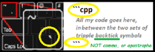
Please edit your last post (using the pencil icon at the bottom) and add-in the backticks etc.
Pete.
Thanks I look but post Mobil and dun know what icon is for close code
What I must do to set code special
I look but dun know what you say so I fix post for you 
As per the Welcome Topic (that everyone reads… right?..) and the above image, it is primarily three backtick keys, before and after the code. Admittedly harder to find on the phone KB, but they are there.
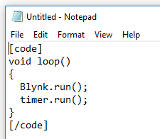
You could try square brackets with “code” and “/code” inside, like this:
Pete.
Ah ok also the normaly form to set code!
Thanks for edit code
I’m sorry i hope that is last one I take some mistake
I’d start with a very simple hardware setup - a switch and an LED.
The switch will become the float eventually, the LED will be replaced by a buzzer and you’ll need to do some work to make it buzz, but keep it simple to start with.
- Read the switch with a timer that samples it every 50 milliseconds.
- When the switch is HIGH (that’s closed, not stoned - we don’t have any groupies yet) you want to turn the LED on as well.
- When the switch goes LOW (that’s open circuit, not a reference to downers) you want the LED to go off.
You’ll need to declare the pins you’re using as inputs (switch) and outputs (LED) using a pinMode statement.
You’ll also need to make sure that you understand that pin D1 on the NpodeMCU isn’t the same as GPIO1. Search for a pinout diagram for your device and study it.
Do some research, experimentation and general playing around until you get this working. If you pass this first test, we’ll help a bit more
Pete.
Ok thanks
I will try out
Some code and I test again every sketch!
I found this sketch but gives blynk every 10 ms a message no matter what position the float switch has. yes it arrives if every 5 seconds of the connection D2 is queried and takes place only every 30 seconds an issue.
You can add the shipping by mail later.
no sound comes out of the buzzer at D7 you do not have to do that somehow by frequency?
/**************************************************************
 * IoT Motion Detector with Blynk
 * Blynk library is licensed under MIT license
 * This example code is in public domain.
 *
 * Developed by Marcelo Rovai - 30 November 2016
 **************************************************************/
#include <ESP8266WiFi.h>

#define BLYNK_PRINT Serial    // Comment this out to disable prints and save space
#include <BlynkSimpleEsp8266.h>
char auth[] = "auth";

/* WiFi credentials */
char ssid[] = "ssid";
char pass[] = "pass";

/* HC-SR501 Motion Detector */
#define ledPin D7
#define pirPin D2 // Input for HC-S501
int pirValue; // Place to store read PIR Value

void setup()
{
  Serial.begin(115200);
  delay(10);
  Blynk.begin(auth, ssid, pass);
  pinMode(ledPin, OUTPUT);
  pinMode(pirPin, INPUT);
  digitalWrite(ledPin, LOW);
}

void loop()
{
  getPirValue();
  Blynk.run();
}

/***************************************************
 * Get PIR data
 **************************************************/
void getPirValue(void)
{
  pirValue = digitalRead(pirPin);
  if (pirValue)
  {
    Serial.println("==> Motion detected");
    Blynk.notify("T==> Motion detected");
  }
  digitalWrite(ledPin, pirValue);
}You have no idea what you’re doing yet, so taking bits of code like this and trying to make them work for you isn’t going to help you.
At this stage you don’t need any Blynk code in there, just code to read a digital pin and echo the output to an LED.
Pete.
1 Like