Good morning to everybody, I’m just starting now with Blynk, I’m having a look on the Blynk documentation, but sorry, but something is still not clear form me!!
I have a datalogger made by Arduino Nano, SD card, LCD display and some kind of sensors.
Now I’m adding to my project an ESP8266-01 through I2C bus and I would see the data on the Blynk app on my phone.
What is not clear for me?
Which setting I must do on the app? (Board: Arduino Nano like “Hardware model” and Wi-Fi like “Connection Type”?)
What kind of code I have to push in Arduino and what kind of code I have to push on the ESP8266?
I’m ok to make ESP8266 stand alone working, I made the first test but now I’m stacked on this, please help me.
The normal way of connecting an ESP-01 that you want to use as a Wi-Fi modem is via serial, not I2C.
If you don’t have a spare UART then use SoftwareSerial and keep the baud rate down to around 9600.
Of course I have the UART available, I would ask a simple example of use.
I wired the ESP8266 to Arduino Nano, wich hardware I have to set on Blynk?
Which sketch and were I have to upload?
I have to use Blynk thinking it is connected straight to NANO and or what?
Example: I have the sketch already running on my device, sensors, LCD, SD card, and everything is fine; I would see the sensor values on Blynk trough a internet connected WiFi ESP8266, what kind of instructions I must follow?
It doesn’t necessarily follow that you’d have a UART available, as you’ll find the ability to use the serial debug monitor very useful and you’ve not said what other hardware you have connected.
How about Arduino Nano and connection type of WiFi?
You upload the sketch to the Nano. The ESP-01 must be running the standard AT firmware and you must have set the baud rate to match whatever you’re using in your sketch.
The sketch builder has plenty of code examples:
Sorry you are right I didn’t mentioned any hardware.
So I upload the AT firmware on the ESP8266 and set it at 9600, I connect it trough UART, on Blynk I set Arduino nano and Serial software, I upload my sketch including the Blynk parts.
On the smartphone I will pair; for example, the led to my physical DO where it is connected the LED itself, in case of graph I associate to the tace the variable and so away…
Sorry but Blynking.begin doesn’t know about SID and Password.
I tried to connect only ESP8266 and it is fine, I have been able to switch a led on and off.
But for me is not clear how to do with my hardware, I’m reading here for two days long, but sorry, I didn’t found any starting explanation with example.
Of course I don’t want a ready made thing, but just a simple way to start
ESP8266 connected to Arduino Nano trough UART, two sensors connected to the Nano trough I2C, a LCD display and a SD card for logging.
I would like to see the datas from remote just to monitor the sensors.
Tonight I connected ESP with AT Fw to Nano and the serial monitor is always showing XXXXXconnecting… row by row scrolling down.
Have a look at the sample sketch from Blynk and tell me where is getting SSID and PASSWORD and how is possible to get connected to the network without them parameters!!!
/*************************************************************
  Download latest Blynk library here:
    https://github.com/blynkkk/blynk-library/releases/latest

  Blynk is a platform with iOS and Android apps to control
  Arduino, Raspberry Pi and the likes over the Internet.
  You can easily build graphic interfaces for all your
  projects by simply dragging and dropping widgets.

    Downloads, docs, tutorials: http://www.blynk.cc
    Sketch generator:           http://examples.blynk.cc
    Blynk community:            http://community.blynk.cc
    Follow us:                  http://www.fb.com/blynkapp
                                http://twitter.com/blynk_app

  Blynk library is licensed under MIT license
  This example code is in public domain.

 *************************************************************
  =>
  =>          USB HOWTO: http://tiny.cc/BlynkUSB
  =>

  You’ll need:
   - Blynk App (download from AppStore or Google Play)
   - Arduino Nano board
   - Decide how to connect to Blynk
     (USB, Ethernet, Wi-Fi, Bluetooth, ...)

  There is a bunch of great example sketches included to show you how to get
  started. Think of them as LEGO bricks  and combine them as you wish.
  For example, take the Ethernet Shield sketch and combine it with the
  Servo example, or choose a USB sketch and add a code from SendData
  example.
 *************************************************************/

/* Comment this out to disable prints and save space */
#define BLYNK_PRINT Serial


#include <BlynkSimpleStream.h>
#include <SoftwareSerial.h>

// You should get Auth Token in the Blynk App.
// Go to the Project Settings (nut icon).
char auth[] = "YourAuthToken";

SoftwareSerial SwSerial(10, 11); // RX, TX

void setup()
{
  // Debug console
  Serial.begin(9600);

  // Blynk will work through SoftwareSerial
  // Do not read or write this serial manually in your sketch
  SwSerial.begin(9600);
  Blynk.begin(SwSerial, auth);
}

void loop()
{
  Blynk.run();
  // You can inject your own code or combine it with other sketches.
  // Check other examples on how to communicate with Blynk. Remember
  // to avoid delay() function!
}
So as to beat others to saying it before you enter code hit 3 back ticks on my keyboard it is just beside the #1 ``` .
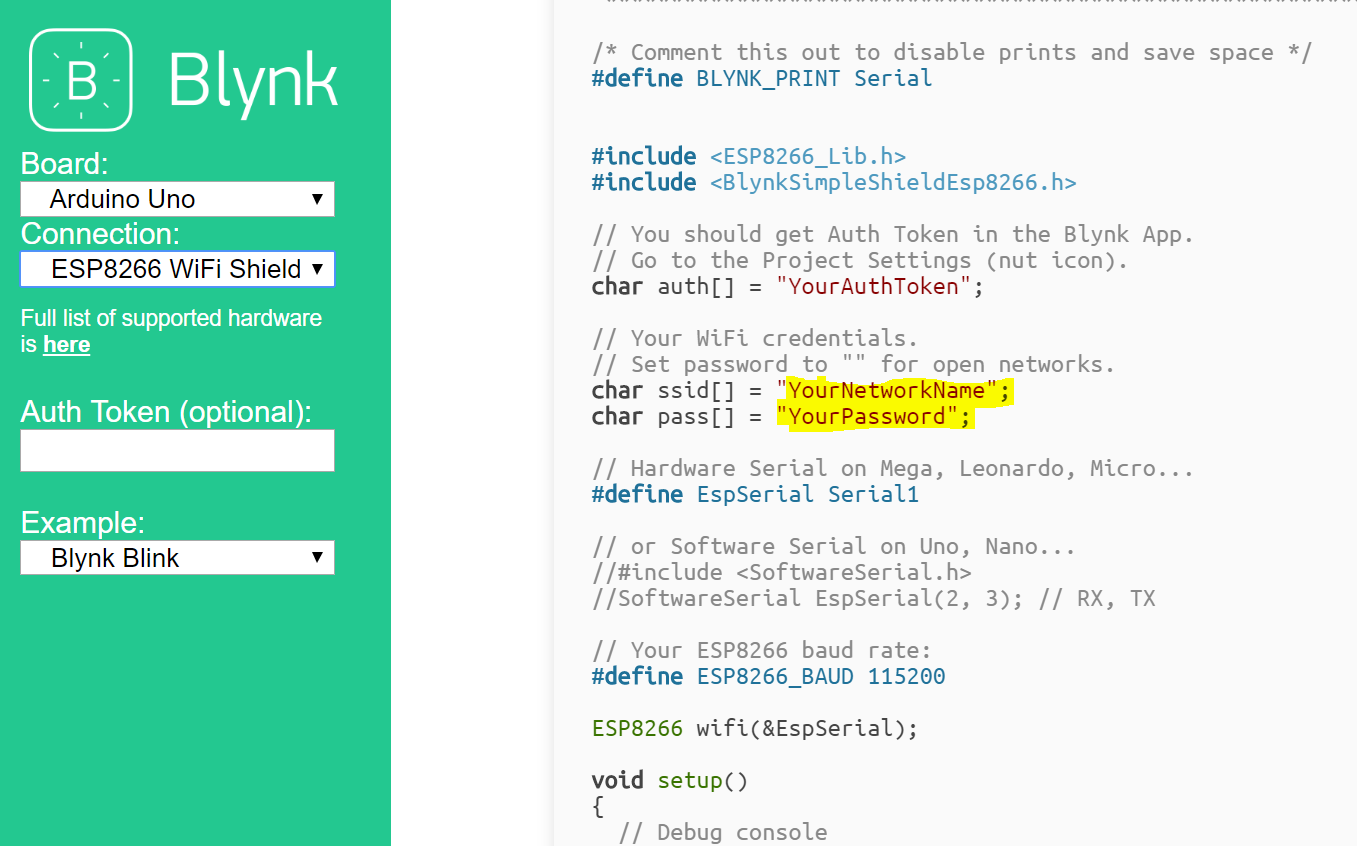
Enter your network credentials in the sketch builder as highlighted in pic.
I think that at this stage it’s worth pointing out that your hardware combination is rather unusual, so you wont find an out of the box solution. Some experimentation will be required, and if you read the code comments, and research the Uno and Mega boards, you’ll see that the Uno has one UART and the Mega has three.
The code says…
// Hardware Serial on Mega, Leonardo, Micro...
#define EspSerial Serial1

// or Software Serial on Uno, Nano...
//#include <SoftwareSerial.h>
//SoftwareSerial EspSerial(2, 3); // RX, TX
in other words, this is universal code that can be used on a variety of different Arduino boards by commenting/deleting some lines of code and removing the code for other lines.
Your initial; post indicated a degree of familiarity with C++ programming and devices, so several of us have made the mistake of signposting you in the right direction without actually going into much detail. Part of the reason for that was probably that we’ve never come across this hardware combination before, but we have no reason to think that it wouldn’t work - with some tweaking of code and experimentation.
If you’re new to coding in general, or to IoT projects, then you might be better looking at a different solution. Personally, I’d be basing this project around a Wemos D1 Mini rather than a Nano + ESP-01