Wonder if you can help. I am controlling several 2 way lighting circuits using an arduino and Blynk. I am using 2 way so I can turn lights on in a garden room by a switch but also remotely with Blynk(via an arduino controlled 2 way relay) from the comfort of my house. Problem I have is that if I turn the lights on via the manual switch I get no update on Blynk to say lights are on and vice versa ie if I turn lights on with blynk and then off with the manual switch, Blynk doesn’t change state of switch to off. You can imagine with 8 channels of this it gets very messy on the Blynk app actually knowing which is on and off!!
So my question is, is there any way to easily do this ?
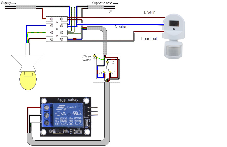
Here is a simple schematic of the relay replacing the second light switch in the two way circuit. I have 8 of these set up.(note there is a PIR also across this particular circuit(outside lights of garden room) just ignore this, but it would be nice if this also updated the the Blynk app with the correct status)
You could try something like a current flow detection device, or this one. No need for the value of the current, just whether it is on or off should be sufficient. Then using that logical on/off determination show the activity in the app with the Blynk.virtualWrite() as @Dmytro mentioned.
I have done something similar (without the active hardware detection) using an app slider and a single physical button/switch combo to control the brightness of an LED
#define WLED 6  // Set Physical LED pin.

WidgetLED WHT(V5);  // Set virtual White LED widget

//===== White LED slider widget - BLYNK Function =====
BLYNK_WRITE(V4)  // Runs everytime White LED slider widget (on V4) is "physically" moved.
{
  brightness = param.asInt();  // Get slider value.
  WHT.setValue(brightness);  // Send slider value to virtual LED.
  analogWrite(WLED, brightness);  // Send slider value to real LED.
}

//===== CodeShield button control of White LED =====
void whiteLED()  // This function checks buttons status and updates White LED and slider (frequency dependent on timer).
{
  if (digitalRead(bUutton) == HIGH and digitalRead(sWitch) == HIGH and brightness < 255) { // Only do something if button pressed and brightness counter in range.
    brightness += 50;  // Increment counter by 50
    Blynk.virtualWrite(V4, constrain(brightness, 0, 255));  // Send constrained (within 0-255) feedback to Slider Widget.
    WHT.setValue(constrain(brightness, 0, 255));  // Send constrained feedback to virtual LED.
    analogWrite(WLED, constrain(brightness, 0, 255));  // Send constrained feedback to LED.
  }
  else if (digitalRead(bUutton) == HIGH and digitalRead(sWitch) == LOW and brightness > 0) {  // Only do something if button pressed and brightness counter in range.
    brightness -= 50;  // Decrement counter by 50
    Blynk.virtualWrite(V4, constrain(brightness, 0, 255));  // Send constrained feedback to Slider Widget.
    WHT.setValue(constrain(brightness, 0, 255));  // Send constrained feedback to virtual LED.
    analogWrite(WLED, constrain(brightness, 0, 255));  // Send constrainedfeedback to real LED.
  }
  else {  // Nothing happening here... move along :)
  }
}
@newdos your physical switches obviously need to be wired to your Arduino / ESP rather than directly to your lights. Arduino / ESP then activates the relays in the same way as Blynk does and then Blynk can read the pin status to update the app.
Dont quite get this gunner - I need to change the state of the button on the app ie when you press it, it states on and when you press it again, it states off. So how does the app get the feedback to change the status of a blynk button, when the physical switch is toggled - does that make sense?
forgive my ignorance as you know very new to Blynk
I was actually giving two answers at the same time, sorry
1st the active sensor could detect if current was flowing, thus on or off, and supply that logic to your MCU (particularly if adapting an existing wiring scenario). otherwise just design everything using relays like @Costas suggested.
2nd, using the Blynk.virtualWrite() command, you can change the state of a widget via code (e.g. move a slider to correspond with a real-world linear potentiometer, or toggle a button widget on/off to correspond with a real world switch - as determined by a current sensor).
But how do I do this when the switch in the drawing is a physical switch in the garden room? I guess what I am trying to do is change the state of a blynk button in the app from on to off or vice versa when the physical switch in the garden room is toggled.
so for info here gunner can you change the state of a widget button with Blynk.virtualwrite() command ? and if so does it need to be connected to a virtual pin rather than a physical pin(which it is at the moment)
Yes… in fact you should always use virtual pins where possible to allow greater flexibility in their use and feedback options.
BLYNK_WRITE(Vx)  // Runs every-time switch widget is toggled.
{
  switchState = param.asInt();  // Get switch value.
  if (switchState == HIGH) {
    digitalWrite(digitalPin, HIGH);  // set digital pin HIGH
  } else {
    digitalWrite(digitalPin, LOW);  // set digital pin LOW
  }
}
@newdos AFAIK the only way is as I described. You can change button states in the app with code but the code needs a signal from somewhere. If you don’t wire the physical switch to the Arduino / ESP then you are never going to know if the lights are on or off.
As stated by @Gunner virtual pins that control digital pins offers much more flexibility and we call them “magic” pins. Unfortunately the magic doesn’t extend to the impossible.
If you didn’t want to mess about with the wiring you could add more Arduino / ESP’s in the garden room with sensors (LDR etc) and they can bridge back to your main Arduino / ESP (with the Bridge widget).
For reference what are you make and model of MCU are you using?
But that’s where a current sensor will make the magic happen - particularly in an already hard wired AC powered environment.
e.g in simple single switch, single light wiring setup, set the current sensor on the return wire from the light. When off, no current, when on, current. sends logical LOW or HIGH to MCU and the code updates the widget.
Thanks guys getting the drift of this now - thats cool that you can change the state of a widget button I didnt know that so will explore that, guess what I need now is some circuit that will give the main feedback to the arduino(safely!!) ie isolated somehow. Anyone here any ideas or done similar???
@Gunner presumably the current sensor reads the mains voltage (110V / 240V). The Pololu is only rated to 30V, even though it is quoted as 30A. 240V sensors do exist though.
Sorry gunner missed the green links!!! yes its 240v here in the UK so I need to sense mains voltage being applied(or taken off) to a physical arduino pin.
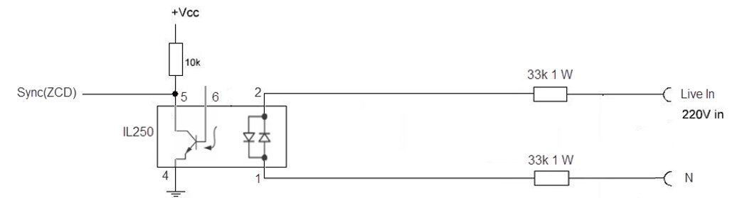
I think I might of answered my question here guys. This circuit is half of an AC dimmer circuit that is zero crossing detecting and feeds and arduino pin using an interrupt to read it. I cant see any reason that this would not work. can anyone tell me if this would be ok and of course it is optically isolated.
Forget to say the live in would be connected to the common of the relay switched by the arduino/Blynk and the Sync would be the detect on the arduino digital pin just using logic 0 or 1