Nice find.
cheers man lets hope it works!!! love this stuff its fab!!!
Im also planning a similar system but without the PIR sensor so keep the thread updated please 
Update: Just figured it out and writing code now. Will share it once im done.
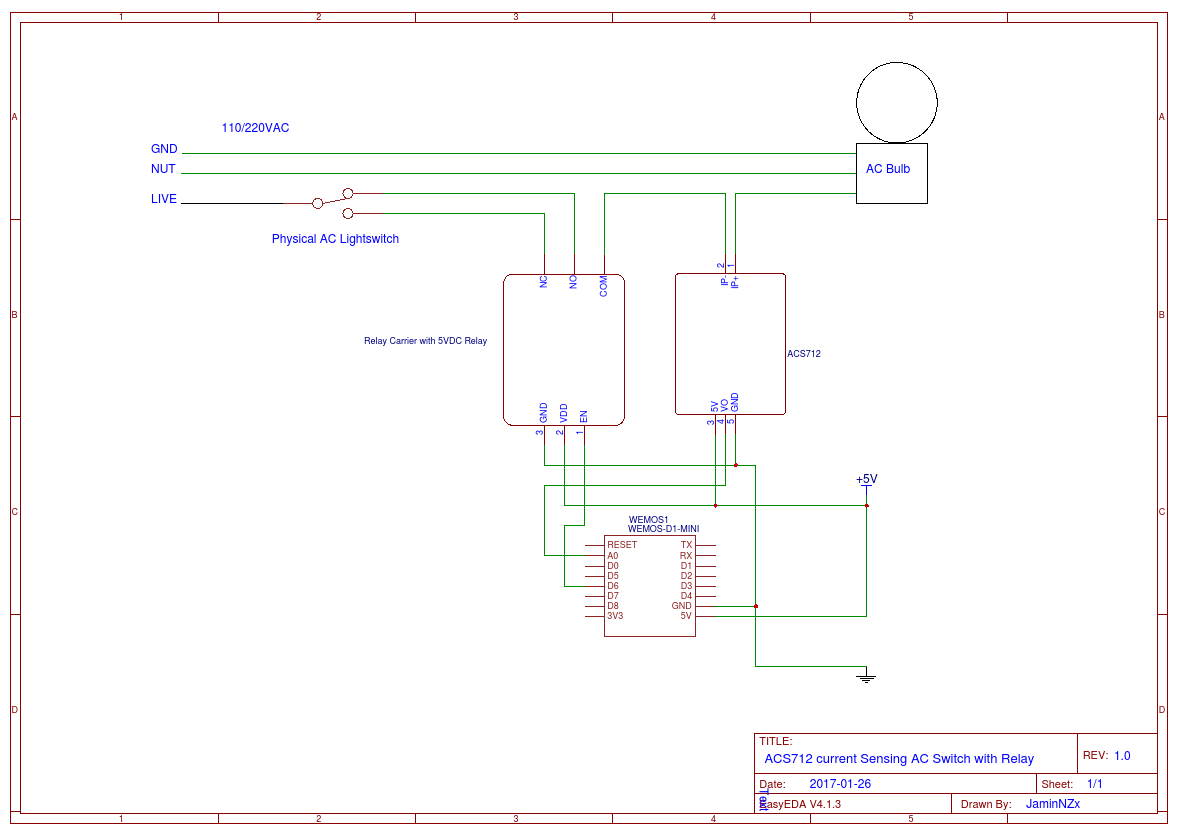
Update2: Here is some working code and diagram to hook it up:
//#define BLYNK_DEBUG
//#define BLYNK_PRINT Serial

#include <ArduinoOTA.h>
#include <ESP8266WiFi.h>
#include <BlynkSimpleEsp8266.h>
#include <SimpleTimer.h>

SimpleTimer timer;

char auth[] = "xxxxxxxxxxxx";
char ssid[] = "xxxxxxxxxxxx";
char pass[] = "xxxxxxxxxxxx";

bool USE_LOCAL_SERVER = 0;

int RELAY_PIN = 14; // GPIO-14 or D5 on ESP8266
int mVperAmp = 100; // use 100 for 20A ACS712 Module and 66 for 30A ACS712 Module
int ACSoffset = 2500;
double Voltage, Amps;

void readACS712() {
  Voltage = (analogRead(A0) / 1024.0) * 5000;
  if (Voltage <= 2500) {
    // detected nothing
    Blynk.virtualWrite(V1, 0); // update LED widget state when detecting current
    Voltage = 2500;
    Amps = 0;
  } else {
    // detected current
    Blynk.virtualWrite(V1, 255); // update LED widget state when detecting current
    Amps = ((Voltage - ACSoffset) / mVperAmp);
    Blynk.virtualWrite(V2, Amps); // report Amps, because why not monitor power usage too?
  }
}

// button control for relay...
// needs to be PUSH type button, detect PUSH only (not RELEASE), and invert relay state
BLYNK_WRITE(V0) {
  if (param.asInt()) {
    digitalWrite(RELAY_PIN, !digitalRead(RELAY_PIN));
  }
}

void setup() {
  pinMode(RELAY_PIN, OUTPUT);
  digitalWrite(RELAY_PIN, HIGH); // most relays are active LOW, so on boot, set HIGH (OFF)

  Serial.begin(115200);
  WiFi.mode(WIFI_STA);
  if (USE_LOCAL_SERVER) {
    Blynk.begin(auth, ssid, pass, IPAddress(192, 168, 1, 2));
  } else {
    Blynk.begin(auth, ssid, pass);
  }
  while (Blynk.connect() == false) {}
  ArduinoOTA.setHostname("AC-Detecting-Switch");
  ArduinoOTA.begin();
  timer.setInterval(1000L, readACS712);
}

void loop() {
  Blynk.run();
  ArduinoOTA.handle();
  timer.run();
}
Cool man that’s great I am going to knock up a single channel version of this on the bench when all the parts arrive. If you have written the code that will be a great test bed for it
Cheers Kev
Ps just seen your code I am using an arduino and wired w5100 Ethernet shield and I will be using the 8ch board listed earlier not the current sensing boards so the code will be some what different I think. Guts of it will be the same though😀
1 Like
Well firstly, it is rated for electrical isolation up to 2.1 kV RMS… I think it can handle a wee little 240v ![]()
And secondly, it wasn’t my insisted upon choice… I had just grabbed a couple of examples after a quick Google search. Mainly to encourage @newdos that it can be done and encourage his own research.
Which it has, and @newdos has found a great multi-connection option ![]() Looking forward to hearing more as you carry on
Looking forward to hearing more as you carry on ![]()
Also note you are doing this with a non latching push switch and a led widget correct? I don’t want to do this i want to use the standard push button widget with no led and change the state of the widget switch when the manual 2 way switch is toggled
Hope that clears up what I am trying to do!!
Cheers
Kev
Cheers gunner but just for the record that board does say a max of 30v
As it was just a reference link and not a breaking point in the overall idea, it wouldn’t matter if it could or couldn’t (the concept is the same)…
…However, I am not sure where everyone is getting that “max 30v” info.
The datasheet clearly says different:
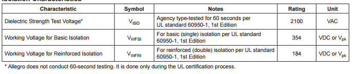
Besides, the Pololu board is for full range current sensing, you just need voltage test, which you have already found. So it is all a mute point.
Those AC detector boards are a bit overkill… the ACS712 can also report current to the Blynk app…handy for calculating watt-hours.
Also those detector boards require 24V… the ASC712 requires only 5V… easyer to hook up
Here is the diagram for the above code:
But do these not require an analog pin for every input as well ???
I read that those boards designed really for Plc require a 5v supply and give a logic 1 or 0 output??
Yes if you look at the diagram, an analog input is required to read the voltage different on the ACS721.
If you are using more than 1 sensor, then yes you will need an ESP32 or UNO/Yun etc… or an ADC breakout for the ESP8266.
Upon detection of positive current, it will light up the LED widget (the state of power)…
If it detects 0 current, it will turn off the LED widget.
You then also have seperate control over the relay using a PUSH button.
The relay is connected so that as long as the physical button and relay are inverted from each other then current will flow.
Hi gunner just so I’m aware of this why does it say have way down the add for the paolo board no higher than 30v??? I’m intrigued is it just a warning to stop people playing with mains ?
Cheers kev
Thanks Jamin but as my early post states I want to use a latching button on blynk app with no led and a physical latching 2nd switch as per normal 2 way circuit
Cheers Kev
You mean SWITCH type button widget? Just change the LED widget to a switch type… it will reflect the state of current… but not the state of the RELAY… so if the relay is ACTIVE… the current might not flow because it depends on the state of the phyiscal switch.
This is why your idea becomes very complicated. Better to read state of current, and light up an LED, then use a PUSH button to change the state of RELAY.
See diagram. There is a physical lightswitch in there.
EDIT: actually… just thought of another way to hook up the button to a SWITCH type widget. brb writing the code
UPDATE: here you go… now the BUTTON (SWITCH type) will light up when Current is detected. If you switch the BUTTON widget off, then current will stop, and the relay will invert its current option.
//#define BLYNK_DEBUG
//#define BLYNK_PRINT Serial

#include <ArduinoOTA.h>
#include <ESP8266WiFi.h>
#include <BlynkSimpleEsp8266.h>
#include <SimpleTimer.h>

SimpleTimer timer;

char auth[] = "xxxxxxxxxxxx";
char ssid[] = "xxxxxxxxxxxx";
char pass[] = "xxxxxxxxxxxx";

bool USE_LOCAL_SERVER = 1;

int RELAY_PIN = 14; // GPIO-14 or D5 on ESP8266
int mVperAmp = 100; // use 100 for 20A Module and 66 for 30A Module
int ACSoffset = 2500;
double Voltage, Amps;

void readACS712() {
  Voltage = (analogRead(A0) / 1024.0) * 5000;
  if (Voltage <= 2500) {
    // detected nothing
    Blynk.virtualWrite(V0, 0); // update BUTTON (SWITCH) widget state when detecting current
    Voltage = 2500;
    Amps = 0;
  } else {
    // detected current
    Blynk.virtualWrite(V0, 1); // update BUTTON (SWITCH) widget state when detecting current
    Amps = ((Voltage - ACSoffset) / mVperAmp);
    Blynk.virtualWrite(V2, Amps); // report Amps, because why not monitor power usage too?
  }
}

// button control for relay...
// needs to be SWITCH type button, detect CHANGE OF STATE only, and invert relay state
BLYNK_WRITE(V0) {
    digitalWrite(RELAY_PIN, !digitalRead(RELAY_PIN));
}

void setup() {
  pinMode(RELAY_PIN, OUTPUT);
  digitalWrite(RELAY_PIN, HIGH); // most relays are active LOW, so on boot, set HIGH (OFF)

  Serial.begin(115200);
  WiFi.mode(WIFI_STA);
  if (USE_LOCAL_SERVER) {
    Blynk.begin(auth, ssid, pass, IPAddress(192, 168, 1, 2));
  } else {
    Blynk.begin(auth, ssid, pass);
  }
  while (Blynk.connect() == false) {}
  ArduinoOTA.setHostname("AC-Detecting-Switch");
  ArduinoOTA.begin();
  timer.setInterval(1000L, readACS712);
}

void loop() {
  Blynk.run();
  ArduinoOTA.handle();
  timer.run();
}
Yes… as they are generally sold to hobbiests, they include a “Cover Their Asp” clause ![]()
But even in the clause, it states…
“Working with higher voltages can be extremely dangerous and should only be attempted by qualified individuals with appropriate equipment and protective gear.”
In other words, certified electricians. Which is why I also included an example for a non-invasive type sensor (usually give its data in the form of resistance value).
Not all, most support 4.5-5v … but as PCL is an industrial rating, thus typically 24v logic, many of these support 24v compliant output levels.
I am done on this topic. Carry on ![]()
1 Like
Thanks for the concise explanation Gunner and all you help bud
Cheers
kev
Thanks Jamin, Wil have a play around with this code as soon as I have time. Juast out of interest (and because I’m at work and dont have time at the moment!) what is the arduinoOTA library, not used this before ???
Cheers
kev
@newdos ArduinoOTA is very powerful. Over the air updates for ESP’s but not available for Arduino’s.
That is why ESP’s are now so popular and generally much more useful than Arduino’s. You can reflash your ESP over the LAN or WAN.
ah ok Costas thanks man thats very cool will have to get into these ESPs - which board should I start with as there seems to be loads of them ??? guess wifi would be good to use ???
Cheers
kev
@newdos it comes down to personal choice and my soldering skills are very limited so take that into account when you read the details below. ESP’s cost around $4 +/- $2 and I have quite a few types.
I have:
1MB 01’s
1MB 07’s with antenna socket
4MB 12’s
4MB WeMos D1 Mini’s
4MB WeMos D1 Mini Pro’s (technically 16MB and has antenna socket)
4MB Wio Link’s
Memory:
The 01’s were originally designed with 512Kb of memory and it is quite difficult to use OTA as the ESP’s needs twice your program size to do the flash. Probably still old stock around but unless they are free don’t bother with them.
The ESP’s with 1MB to 4MB can only use the first 1MB for program memory so unless you want to store your webserver in the area above 1MB it generally goes unused. The Pro has 16MB of memory that gives 15MB of storage space but until the ESP core code is updated it is currently only working as a 4MB module.
Board layout
The 01, 07 and 12’s are bare chips and you have to add components to make them work.
The WeMos, Wio Link and nodeMCU (that I don’t have) are complete, ready to go devices with USB ports. As the ready to go units are only a couple of dollars more then they are my preferred choice. If you have a project that needs hundreds of ESP’s and 512kb is enough memory then you might want to consider bare chips. It’s certainly not something I would consider.
Antennas
During your “bench tests” antennas are not that important but when you fit the ESP’s in a case and move them to your garden house, loft, basement etc they are very important.
My current favourite is the WeMos D1 Mini Pro for $5 plus delivery costs.
4 Likes