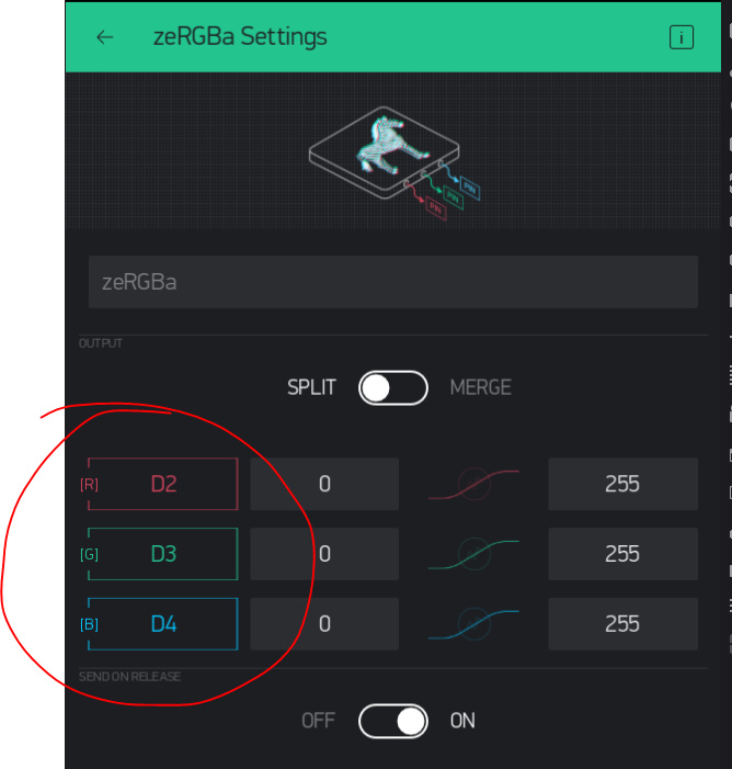
I’ve recently gotten into electronics and programming, meaning I’m quite new to both. Nonetheless I made my first project this week where I’m using an esp8266 board to control an led strip with my phone. I heard about Blynk, and I’m loving it! At the moment I have this code, which allows me to use the zeRGBa widget:
It’s incredibly simple, one of the examples, but it works and my focus was mostly on the electronics anyways. I do have two questions though, which would be great if someone could help me with:
I had a slider for brightness and an switch for on/off in mind. Is this possible? For the slider I’m not sure, but for the switch I don’t think it is: I can only enter one pin - not all three for r g b channels and cut power that way. Those pins are already in use for zeRGBa anyways… Of course the power for the RGB strip is also routed directly to 12v, since the esp8266 cannot output that.
Is there a workaround or alternative method? This leads on to my next question:
It seems really cool! However, I’m not too sure on how I’d incorporate the code into my sketch.
One thing I don’t understand is where to put what - the example tells me that there are two sections: the void setup which runs once and the void loop which runs twice. Do I keep these and put sections of the code gunner supplied underneath them, or do I get rid of them? I also need to add wifi and authentication token but I can do that above, correct?
I also tried verifying the code, but it says that the rrr, bbb and ggg sections consistently used throughout the code is not defined.
So generally, if someone could help me with understanding gunner’s code and where to substitute what I’d be really grateful.
Glad you liked the idea… that was more an exercise in control data translation (the Zebras 0-255 into the Blynk.setProperty()#HEX)
But that is not necessarily easily transferable into RGB light strips as they require other library control (Adafruit or FastLED) of the individual LEDs via single pin digital codes
EDIT - that particular code was just a portion of a much larger project… so all the picky define details etc. were not included… although I think I did post a more completed example or two somewhere… search for zeRGBa
This is not a “how to program” forum, but you can probably figure it out with some learning about Arduino C++ programming syntax. And that is best learned over time and with beginning level projects
Exactly what RGB strips are you using? Most I have used run on 5v MAX. And besides, dimming is NOT controlled via that voltage, rather all power, LED colour/positioning/intensity, etc. are handled via the RGB strip library and programming control
I’m using 12v rgb led strips - not the individually addressable ones (these run on 5v). They have four channels, three for rgb and one for power. By supplying power and grounding one of the rgb channels that colour is turned on. The esp8266 can then turn on any colour by sending different pulses to the different rgb channels (of course there’s more circuitry in between the esp and the led strip but that’s the basic idea.
Oh, I thought I’d seen you recommending that code to people who wanted to use it for rgb strips. Maybe they used it for simple led’s? Anyways, do you know a solution - a way to turn the led strip on/off with a widget? Or use separate sliders similar like you did?
OK, there must be some example code that will allow that pulsed control, is it PWM or something proprietary?
Once it is determined how to set those pulses, it might be possible to control them with the Blynk Widgets… but is not necessarily a case of simply linking a widget to a digital pin… more like lots of code writing.
I assume that you’re using some N-Channel MOSFETS to drive the LED strip, like this:
The code is pretty simple, but varies slightly between Arduino and ESP/NodeMCU because the Arduino will use 255 PWM steps to go from off to 100% brightness, but the ESP uses 1024 steps.
Yes, it’s simple PWM per channel. I already figured out how to link the zeRGBa for each channel, in the way you said - I thought I mentioned that in my post. What I was trying to do was use figure out a way to dim the rgb strip as a whole and turn it off/on with a widget. If I had the power for the strip coming from the esp8266 then I could use that pin to turn it off/on by directly linking the switch widget to the pin. However, that’s not the case. So my question was for a workaround - maybe with individual sliders (allowing me to slide them all down for on/off and also better brightness control, in a way similar to your example that I mentioned in my post.
OK, yes, then you would need to switch to using virtual pins and coded control routines on the device.
Strip intensity control must come from the matched reduction of the PWM values across the channels, NOT the supply voltage.
Are you aware the zeRGBa already incorporates this intensity control via it’s vertical placement of the touch point? - How add brightness to zeRGBa?
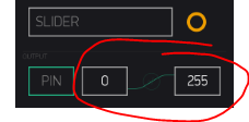
And for example of virtual pin control of a PWM digital pin… this is a very simple, single channel, PWM pin control from a slider on V0 set with a range of 0-1024
BLYNK_WRITE(V0)  // This functionRuns every time LED slider widget is adjusted
{
  analogWrite(PWMpin, param.asInt());  // Send slider value (storred in param.asINT() )to real LED.
}
Personally, I’m not a great fan of the ZeRGBa widget. I use sliders for each colour, but link these to virtual pins rather than digital pins. The drawback to this method is that more coding is required, which I think may be an issue for you?
Using virtual pins makes it easy to switch all three colour channels off at the click of a button without touching the sliders, but your code would need to incorporate a conditional statement that checks the state of the on/off widget and outputs 0 to each color channel if it’s off, or whatever the slider preset value is if the switch widget is on.
Thanks, that’s helpful. Two questions - how does it know where to send the slider value? Do you not need to specify the digital pin - would you substitute that under pwmpin?
Also, you said it’s set with a range of 0-1024, but I don’t see that specified anywhere.
That sounds like something I’d want to achieve! You’ve given me a rough idea - now I just need to teach myself how to code that
I might have a look online and figure out ways to do that if I have time… Otherwise I guess I’ll just use my zeRGBa widget.
I don’t fully grasp the virtual pin idea though. So if I understand correctly, I would use a conditional statement in the way you said, effectively providing a link between the virtual pin and the three colour channels?
Do you think it would be achievable for a beginner to code this without sinking too many hours in learning it? Would I also be able to code it so that I can use the three sliders in conjunction with the zeRGBa widget?
If you used a virtual pin for each slider then in your code you’d write the value obtained from the virtual pin to the digital pin controlling that colour in your hardware (once you’d checked the virtual pin that the on/off switch widget is connected to, to make sure that the switch widget is on).
The range for an ESP/NodeMCU device is 1024 steps, so 0-1023 (or 1-1024).
Add these into the pre-setup part of the example code you already found from me… I think it covers all the variable defines.
Adjust for your digital pin usage.
int rrr, ggg, bbb;  // Set RED BLUE GREEN channels
#define RedP 11  // Set RED RGB pin.
#define GrnP 10  // Set GREEN RGB pin.
#define BluP 9  // Set BLUE RGB pin.
And in the setup loop()
pinMode(RedP, OUTPUT);  // Set RED on RGB LED.
pinMode(GrnP, OUTPUT);  // Set GREEN on RGB LED.
pinMode(BluP, OUTPUT);  // Set BLUE on RGB LED.
Sorry Pete, I understand that - I was referring to the switch. I’ll repeat my question: How would I go about turning all three off with the switch of a button? With the conditional statement including the statement of the switch and then providing a signal to three virtual pins, each linked to a digital pin controlling a colour channel?
Right. But I have a slider with a digital pin for each colour channel, and then I want a switch to turn them all off/on. So can I code it so that the blynk button changes the on/off status of a virtual pin, and that the virtual pin then sends a signal to the three digital pins?