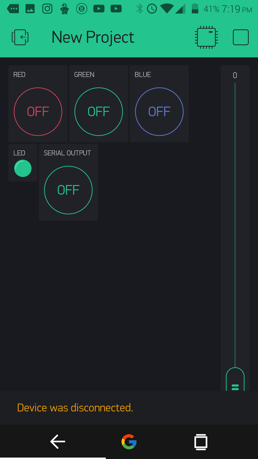
I am doing a project a got stuck and I need your help. It consists of an RGB led strip on the hardware side. In the blynk app I have 3 Buttons to control Red,blue,green colors , a slider to control the brightness of the leds and a widget led. Every thing works fine but I can not get the widget led to work properly. It is suppose to display the color of the actual led strip on the app. So that I can see what the color is from the app. The widget led is diplaying red,green and blue colors randomly even if the leds ar turned off. Can someone check my code and see where is the problem?
#include <SimpleTimer.h>
#define BLYNK_PRINT Serial    // Comment this out to disable prints and save space
#include <ESP8266WiFi.h>
#include <BlynkSimpleEsp8266.h>

WidgetLED led(V10);

SimpleTimer timer;

char auth[] = "5xxxxxxxxxxxxxxxxxxxxxxxxxxxxxxxxa2";
char ssid[] = "Claxxxxxxxxxxxxxi";
char pass[] = "cxxxxxxxxxxxxxxxx";

//Widget Colors ----------------------------
#define BLYNK_Green     "#23C48E"
#define BLYNK_Blue      "#04C0F8"
#define BLYNK_Red       "#D3435C"

#define BLYNK_White     "#ffffff"
//-------------------------------------------

int redval;
int greenval;
int blueval;

// Physical led pins

#define redpin 14
#define greenpin 13
#define bluepin 12


int brightnessval; // brightness value


void ledwidget() {
  if (redval > 1) {
    led.on();
    led.setColor(BLYNK_Red);
  }
  else
  {
    led.off();
  }

  if (blueval > 1) {
    led.on();
    led.setColor(BLYNK_Blue);
  }
  else
  {
    led.off();
  }

  if (greenval > 1) {
    led.on();
    led.setColor(BLYNK_Green);
  }
  else
  {
    led.off();
  }

}


void setup()
{

  Serial.begin(9600);
  Blynk.begin(auth, ssid, pass);

  pinMode(redpin, OUTPUT);
  pinMode(bluepin, OUTPUT);
  pinMode(greenpin, OUTPUT);
  analogWrite(redpin, 0);
  analogWrite(greenpin, 0);
  analogWrite(bluepin, 0);
  timer.setInterval(2000L, ledwidget);
  brightnessval = 1023;
}


BLYNK_WRITE(V0) // Red Color

{
  if ( param.asInt() == 1 )
  {
    analogWrite(redpin, brightnessval ) ;    // for switching on at brightness level
    redval = analogRead(redpin);
  }
  else
  {
    analogWrite(redpin, 0) ; // for switching off

  }

}
BLYNK_WRITE(V1) // green color
{
  if ( param.asInt() == 1 )
  {
    analogWrite(greenpin, brightnessval);
    greenval = analogRead(greenpin);

  }
  else
  {
    analogWrite(greenpin, 0 );


  }
}


BLYNK_WRITE(V2) // blue color
{
  if ( param.asInt() == 1 )
  {
    analogWrite(bluepin, brightnessval );
    blueval = analogRead(bluepin);


  }
  else
  {
    analogWrite(bluepin, 0);

  }
}

BLYNK_WRITE(V16)
{
  brightnessval = param.asInt(); // assigning incoming value from pin V1 to a variable
}

BLYNK_WRITE(V11) // White color
{


  int white = param.asInt();
  analogWrite(redpin, white) ;
  analogWrite(greenpin, white) ;
  analogWrite(bluepin, white) ;


}


BLYNK_WRITE(V7) // for testing purposes
{
  // Change state on button press
  if ( param.asInt() == 1 ) {
    Serial.println("Green Value");
    Serial.println(greenval);
    Serial.println("Red Value");
    Serial.println(redval);
    Serial.println("Blue Value");
    Serial.println(blueval);


  }
}


  void loop()
  {
    Blynk.run();
    timer.run();
  }
But even if I just turn on a single color it is still not working correctly and actually the final project will have a zeRGBa widget but I just simplified to project for now.
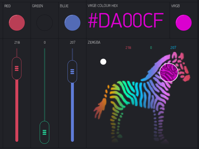
@claytoncamilleri100 Here is some code I have used to utilise both the zeRGBa and three sliders to adjust physical and widget based LED’s. (adjusting the zeRGBa also adjusts the individual sliders accordingly - showing both the mixed and individual colours as well as intensity).
The key to getting a “close” resemblance between the physical and virtual is to convert the physical RGB pin data to HEX and send that back to the widget LED via Blynk.setProperty(Vx, "color", HEXstring); // Send formatted HEX colour to vRGB.
This is just part of a larger project, so you will have to extrapolate the code & variables and make adjustments to the virtual pin numbers so that it corresponds with your sketch and app.
BLYNK_WRITE(V20)  // RED slider
{
  rrr = param.asInt(); // get a RED channel value.
  Blynk.virtualWrite(V23, rrr);  // Set RED vLED intensity
  RGBprocess();  // Goto pin data to HEX conversion function.
}
BLYNK_WRITE(V21)  // GREEN slider
{
  ggg = param.asInt(); // get a GREEN channel value.
  Blynk.virtualWrite(V24, ggg);  // Set GREEN vLED intensity
  RGBprocess();  // Goto pin data to HEX conversion function.
}
BLYNK_WRITE(V22)  // BLUE slider
{
  bbb = param.asInt(); // get a BLUE channel value.
  Blynk.virtualWrite(V25, bbb);  // Set BLUE vLED intensity
  RGBprocess();  // Goto pin data to HEX conversion function.
}

//===== zeRGBa widget  - BLYNK Function =====
BLYNK_WRITE(V2)  // zeRGBa widget
{
  rrr = param[0].asInt(); // get a RED channel value.
  ggg = param[1].asInt(); // get a GREEN channel value.
  bbb = param[2].asInt(); // get a BLUE channel value.
  Blynk.virtualWrite(V20, rrr);  // Red slider position.
  Blynk.virtualWrite(V23, rrr);  // Red LED intensity.
  Blynk.virtualWrite(V21, ggg);  // Green slider position.
  Blynk.virtualWrite(V24, ggg);  // Green LED intensity.
  Blynk.virtualWrite(V22, bbb);  // Blue slider position.
  Blynk.virtualWrite(V25, bbb);  // Blue LED intensity.
  RGBprocess();
}

//===== Physical RGB LED Control and HEX conversion =====
void RGBprocess()  // Do all the pin value to HEX conversion, and display it to app widgets
{
  analogWrite(RedP, rrr);  // Write to RED RGB pin.
  analogWrite(GrnP, ggg);  // Write to GREEN RGB pin.
  analogWrite(BluP, bbb);  // Write to BLUE RGB pin.
  String strRED = String(rrr, HEX);  // Convert RED DEC to HEX.
  if (rrr < 16) {
    strRED = String("0" + strRED);  // Buffer with 0 if required.
  }
  String strGRN = String(ggg, HEX);  // Convert GREEN DEC to HEX.
  if (ggg < 16)  {
    strGRN = String("0" + strGRN);  // Buffer with 0 if required.
  }
  String strBLU = String(bbb, HEX);  // Convert BLUE DEC to HEX.
  if (bbb < 16)  {
    strBLU = String("0" + strBLU);  // Buffer with 0 if required.
  }
  String HEXstring = String("#" + strRED + strGRN + strBLU);  // Combine HEX fragments.
  Blynk.run();
  HEXstring.toUpperCase();  // Change HEX value to all upper case for ease of visuals.
  Blynk.setProperty(V8, "color", HEXstring);  // Change background colour of HEX Data Label.
  Blynk.virtualWrite(V8, HEXstring);  // Display HEX data.
  Blynk.setProperty(V9, "color", HEXstring);  // Send formatted HEX colour to vRGB.
  Blynk.virtualWrite(V9, 255);  // Activate vRGB.
}