Which board should I choose for my first Blynk project?

I thought I’d write a piece about my thoughts on the best hardware to use for your IoT projects if you’re just starting-out with Blynk.

I did what many people do, started-off buying an Arduino Uno and uploaded some code to make it flash an LED. After about 10 seconds of watching the LED flash I was bored, and wanted to do more (I have a short attention span :sleeping:).

The next task was getting the Uno connected to the internet and I chose the Ethernet Shield route. After around 6 months of messing around with the Ethernet shield (I’m also very persistent :confounded:) and experiencing regular problems, especially when the Uno was restarted, I decided that the Ethernet shield had to go.

I started looking at alternatives and came across the ESP-01, so ordered one, but while I was waiting for it to arrive I realised that the ESP range of boards could also be programmed via the Arduino IDE using basically the same code as the Uno. After a bit more research I decided that the NodeMCU board was worth investigating, so ordered one of those and pretty soon the Uno was gathering dust.

After a while I switched to using the Wemos D1 Mini (not to be confused with the Wemos D1, which is basically a Uno with an ESP-01 chip attached) and that’s now my “go-to” board for all of my IoT projects. I use this board because it works well for the type of projects that I do, and it obviously won’t be the best choice of board for everyone.

I’ve chosen to compare 5 basic boards which are readily available ‘mainstream’ products that should be on the shortlist for an IoT beginner. These are (left to right in the photo below):

  • Arduino Uno
  • Arduino Mega
  • ESP-01
  • NodeMCU
  • Wemos D1 Mini

I also give a mention to the Wemos D1 Mini Pro, mostly because I’m now drifting towards using this as my day-to-day board.

There are other boards available, including the ESP32 (which will probably become the preferred choice of board for many in the future) and some slightly less mainstream boards like the ones from Adafruit and Particle. There is also the Raspberry Pi, but in my opinion the Pi is better suited to being a local Blynk server than a client device.
However, when it comes to simplicity and ease of learning for newcomers, I think you’d be better limiting your choice to one of these 5 (or 6 if you include the D1 Mini Pro) as your starting point. These boards are all fairly cheap and readily available, so you can usually get up and running fairly quickly. If you decide you want to try less mainstream alternatives in future then what you’ve learned using one of these boards will provide you with valuable knowledge and experience.

I’m not going to discuss Bluetooth/BLE or USB serial connection methods, as I don’t think these have a real role in most IoT projects, so I’m going to assume that you want a board that is Wi-Fi capable - either with native Wi-Fi support or by using an ESP-01 as a Wi-Fi modem.

Here’s a table showing the main features of of these 5 (okay, it’s 6 really) boards:

MCU Memory Clock Speed Logic Voltage GPIO Pins Analogue Pins Approx Cost (USD)
Arduino Uno 32 KB 16MHz 5v 14 6 $3.00
Arduino Mega 256 KB 16MHz 5v 54 16 $8.50
ESP-01 512 KB - 4MB 80MHz/160MHz 3.3v 2 0 $1.60
NodeMCU 4MB 80MHz/160MHz 3.3v 11 1 $2.30
Wemos D1 Mini 4MB 80MHz/160MHz 3.3v 9 1 $2.10
Wemos D1 Mini Pro 16MB 80MHz/160MHz 3.3v 9 1 $3.60

Prices are based on a quick search of AliExpress and based on buying one board. I’ve gone for the sellers who offer free postage (to the UK) and chosen to use the universal currency of US Dollars. Delivery times tend to be quite long when buying from AliExpress, Bangood or Chinese sellers on eBay and if you’re like me you want it, and you want it NOW, which means you’ll probably pay more to buy from a local retailer selling on eBay.

Here’s a quick summary and Pros and Cons of each device (as I see them):

Arduino Uno

The Uno is the standard entry point for many people wanting to dabble with microprocessors, but its main disadvantage is that it has no way of connecting to the internet without adding either an Ethernet shield or a Wi-Fi modem (usually an ESP-01), so in its standard form it isn’t an IoT device.

The Ethernet shield is notoriously unreliable, and hooking-up to an ESP-01 has a few pitfalls that can catch beginners out.

Advantages

  • 16 GPIO and 6 Analogue pins

  • 5v logic levels (can also be a disadvantage)

  • Can be programmed via the Arduino IDE

Disadvantages

  • No Ethernet or Wi-Fi connectivity without additional hardware

  • Limited memory

  • Slow processor speed

  • OTA not available

  • Physical size

Arduino Mega

The big brother of the Uno, it still has many of the Uno’s disadvantages. The main plus points are more serial ports, which makes adding an ESP-01 Wi-Fi modem simpler, and a bit more memory. It obviously has more GPIO and Analogue pins, but seriously, how many do you need on one device? (I’ll discuss this more later).

Advantages

  • 54 GPIO and 16 Analogue pins

  • 5v logic levels (can also be a disadvantage)

  • 4 Serial interfaces (UARTs)

  • Can be programmed via the Arduino IDE

Disadvantages

  • No Ethernet or Wi-Fi connectivity without additional hardware

  • Limited memory (better than the Uno, but still low)

  • Slow processor speed

  • OTA not available

  • Physical size (even bigger than the Uno)

  • Higher price

ESP-01

The ESP-01 is often used with the standard “AT” firmware to act as a serial modem for an Arduino Uno or Mega, bit it actually has more processing power and memory than either of these Arduino devices.

The ESP-01’s main feature is that it’s tiny, so can be used to add IoT capabilities to existing hardware.

Advantages

  • Physical size

  • Can be updated using OTA (the 1mb and 4MB versions are better for this)

  • Can be programmed via the Arduino IDE (after installing an add-in)

Disadvantages

  • Lack of available GPIO pins

  • No Analogue pin

  • 3.3v logic levels (can also be an advantage)

  • Pin layout can be difficult to work with

  • No on-board serial to USB adapter, so needs a separate USB (FTDI) adapter to be able to flash code to the device

  • GPIO0 needs to be manually pulled low when flashing code to the device (except if OTA is used)

  • Several different variants with different memory sizes, can be difficult to know what you have

NodeMCU

The NodeMCU ought to be the entry point for anyone wanting to experiment with IoT. It is easy to work with, has built-in Wi-Fi connectivity and enough memory to handle most sketches and still be able to be updated via OTA.

Advantages

  • Built-in Wi-Fi modem

  • Large memory and fast processing speed

  • Can be updated using OTA

  • Physical Size

  • Can be programmed via the Arduino IDE (after installing an add-in)

Disadvantages

  • The two rows of pins are too far apart to work well with most breadboards

  • Fewer GPIO pins than the Arduino boards (and care needs to be taken when choosing which pins to use)

  • Only one Analogue pin

  • 3.3v logic levels (can also be an advantage)

  • Pin numbering can be confusing

Wemos D1 Mini / Pro

This is really a variant of the NodeMCU on a slightly smaller board. Fewer GPIO pins are available, but the narrower distance between the two rows of pins makes it easier to use with breadboards. There is also a large range of ‘shields’ that can be used with these boards.

The Pro version has an external antenna connector. To use this a surface mount zero ohm resistor has to be re-soldered in a slightly different position. The Pro also has more memory, but this can’t be utilised in most situations.

Advantages

  • Same as NodeMCU except the smaller board works better with breadboards

  • Wide range of accessories that use the same format

  • The Pro version can be used with an external Wi-Fi antenna for extra range

  • Supplied with no pins soldered in place, so has greater flexibility (also a disadvantage?)

Disadvantages

  • Same as NodeMCU plus:

  • Fewer GPIO pins than the NodeMCU

  • Basic soldering skills required

.
GPIO and Analogue Pins - Do the Numbers Matter?
General Purpose Input/Output (GPIO) pins are used to connect digital input devices like sensors and output devices like relays. Generally, one GPIO pin is needed per sensor/relay, as the other side of the circuit is connected to ground.

Analogue pins are used when it’s necessary to measure the voltage that’s being received from a sensor.
You might think that things like temperature and humidity sensors would output analogue values, but that’s not the case with modern sensors. Virtually everything now is digital, as it provides a much more stable and interference-free way of communicating between devices.

Many modern sensors are multi-functional, so something like the BME280 can measure temperature, humidity and atmospheric pressure using a single sensor and one GPIO pin.

This meas that you don’t really need many GPIO pins to build a fairly sophisticated device. Something like a thermostat with a digital display could need:

  • 1 GPIO for the sensor
  • 1 GPIO for a relay to turn the heater on/off
  • 2 GPIOs for an OLED display
  • 3 GPIOs for an auto/manual switch and up/down temperature buttons

A total of 7 GPIO pins to build a fairly sophisticated thermostat unit.

Okay, I hear you say, but I want to measure outside temperature as well, and maybe wind speed, rainfall, and light levels; and I want to open and close the garage doors, turn the garage lights on automatically and measure the temperature in the garage as well.
That’s all fine, but you wouldn’t use a single microprocessor to do all of those things. There would be a separate one on the roof acting as a weather station, and another one in the garage making sure your car is nice and cozy. Rather than running a rats nest of wires to a single control point with one microprocessor board, you’d have a dispersed system - with a separate microprocessors performing a dedicated range of tasks.

I actually have 9 different microprocessors in my living room. Some of these are built-in to Sonoff S20 type sockets that control lighting, or are built-in to RGB controllers that also control lighting. Others take temperature readings, transmit Infrared signals to devices, transmit and receive 433MHz radio signals or control a touch screen display. Having all of these controlled by one microprocessor device isn’t practical because it would mean running wires between each sensor or item that is being controlled. By using dispersed ESP8266/NodeMCUs that are controlled via Wi-Fi makes for a very neat solution, but each of these microprocessors only uses two or three of its available GPIO pins to do its dedicated task.

Edit May 2020 - another alternative to solving the problem of needing more GPIOs is to use a port expander such as the MCP23017 and that’s covered in detail in this topic:

I mentioned earlier that care needs to be used when choosing which GPIO pins to use on a NodeMCU or Wemos D1 Mini. There is more on that subject in this topic:

GPIO Voltages - 3.3 or 5 volts?
The Arduino Uno and Mega, along with most of the other Arduino variants, uses 5 volt logic levels for its GPIO pins. This means that setting one of the GPIO pins HIGH will result in 5v being applied to that pin. When signals are passed between sensors then these signals will switch between 0 and 5v at high speed.

The ESP98266/NodeMCU devices (including the Wemos) operate at 3.3v logic levels. It’s been shown that these devices can tolerate having 5v applied to their GPIO pins, when connecting them to sensors that output a 5v logic signal, but it’s generally regarded as a ‘do it at your own risk’ approach.

However, most modern sensors are compatible with both 3.3v and 5v boards, so can be used without risk of damaging anything. All modern boards use 3.3v logic, so at some point you may find that it’s the Arduinos that are incompatible with the newer sensors.
If you do need to convert between 3.3v and 5 logic levels then it’s very easy using a simple board like this, which costs around $0.50

I’ve only needed to use one of these once, to interface a RFID card reader to a Wemos D1 Mini for my door entry system (more on that below).

GPIO Pin Numbering on the NodeMCU/Wemos D1 Mini Boards
One thing that catches many people out when they start experimenting with NodeMCU/Wemos D1 Mini type boards is the strange pin numbering that the manufacturers adopted. Don’t ask me why they did it, we just have to be aware of it and live with it.

They pins have numbers like D1, D2, D3 etc and it’s logical to assume that these represent GPIO1, GPIO2 and GPIO3, but these pins are actually GPIO5, GPIO4 & GPIO0.

You need a diagram like this close to your desk when you’re wiring things up:

What is OTA, and Why Does it Matter?
I’ve mentioned OTA in my comparison of various devices, and some newcomers may not be aware of what it is and why It’s so useful.

OTA stands for Over The Air, and is basically a way of flashing new code to your board without having to physically touch it. The new code is sent via Wi-Fi, so the board could be in an inaccessible place, or in a piece of hardware that requires significant disassembly to reach the board and plug a USB cable into it.

OTA requires a few add-ons to be installed on the computer that is running the Arduino IDE and a few extra lines of code to be added to the sketch that’s uploaded to the board when you first program it. After that, the board appears as a virtual port in the IDE and a new sketch be pushed out to it without even having to leave your chair.

The new sketch is uploaded to the board alongside the old sketch, then the board reboots and the new
sketch is used. For this reason, the board needs at least 50% of its memory to be available, so ESP-01s with 512KB of memory don’t really have enough memory for OTA. The 1MB versions are okay if you have a fairly basic sketch that you want to upload.

OTA only works with ESP8266 based boards (this includes the ESP-01, NodeMCU and Wemos boards). It can’t be used with Arduino boards, or ESP-01 that are being uses as a Wi-Fi modem for an Arduino.

A Bit More About Wemos Accessories
There are a wide variety of accessory ‘shields’ that can be used with the Wemos D1 Mini/Pro range of boards, including double and triple bases, relays, OLED displays, sensors, switches, motor control shields, MicroSD card readers, prototyping boards etc.

These can either be stacked piggyback style on top of each other (the boards come with a variety of different connectors and you have to put some thought into the type of connectors you solder to the boards if you want to use them this way) or they can be positioned side by side on the double or triple bases. (You could actually do both - stacking and side by side - if you wish).

Here’s a picture of the door entry project I mentioned earlier. Wemos D1 Mini Pro (with external antenna connected) on the left, relay in the middle, and a prototyping board with the logic level shifter and a voltage regulator circuit on the right. All plugged-in to a triple base, giving the ability to easily swap components out if needed.

I do have a few situations like this one where I need to attach an external antenna to a Wemos board, so I’m tending to order batches of the Pro version of the board so that I have the option to add an antenna to any of my boards if I need to.

So, Which Board Should You Choose?
Everybody will have different requirements and priorities, and you should choose a board that is the best fit for the project(s) you have in mind.

If you want to monitor the voltages on a bank of 30 batteries, which will need lots of analogue inputs, then the Arduino Mega is probably your best bet.

If you want something tiny that will fit inside your existing smoke detector to turn it into a smart detector then probably the ESP-01 is the best choice.

If you’re doing a school or university project and your teacher has told you that you must use an Arduino Uno then take your teacher on one side and tell them that “Uno’s are SO not cool” (or whatever that translates to nowadays).

For someone who just wants to buy a board that can be used as a test-bed, but which can ultimately be used as the MCU in a serious project then the NodeMCU or Wemos D1 Mini is what I’d recommend.

I’m sure there’ll be dozens of people who chip-in with differing views, and there will probably some who may agree as well. What’s important is that you choose a board that’s right for the project you have in mind, and hopefully this thread will help to narrow-down the choices and make an informed decision.

If you’re still confused just buy a Wemos D1 Mini (or two) :smiley::smiley::smiley:

Pete.

21 Likes

nice writeup!

1 Like

Great summary. I have purchased NodeMCUs that have been breadboard friendly and unfriendly. I have found that NodeMCUs with “Amica” stenciled with a white background on the backside are breadboard friendly.

3 Likes

@PeteKnight This is a perfect, in all aspects, documentation for the subject, congratulation Pete !

1 Like

Hi Pete,
Thanks a lot for this work.
I see that you re using wemos D1 mini pro with external antenna. Does it improve a lot the quality of wifi ?
And to you have any comparison on consomption ?
Regards

Hi @laurent, one of the locations where I needed to fit a Wemos was outside, in a box that was going to be both strong and waterproof. I decided to use a diecast aluminium box, which meant that the Wemos was almost totally shielded. Using a Pro board and external antenna was an easy fix.

I also have another location where the the Wi-Fi signal is fairly weak and I’ve used used a similar solution there.
I’ve found that the antennas you buy on eBay vary enormously in terms of gain, and as I don’t have an antenna tester I used the ‘trial and error’ method, by monitoring RSSI values to find the most efficient type of antenna in a given location.

If you do use an external antenna with a Pro, you need to move the zero ohm resistor, otherwise the external antenna will make no difference.

I’ve not done any power consumption comparisons. Are you thinking of using deep sleep mode? If so, then you may want to consider an ESP8266 board that doesn’t have an onboard USB interface and 5v regulator - maybe one of the Sparkfun boards.

Pete.

ok. Too bad that using external antenna needs to move the resistor. I think I’ll start playing with solder irons an other day.
I was able to improve wifi connection sending rssi (“WiFi.RSSI() function”) to a Superchart. I could then improve configuration of my wifi router.

deep sleep mode is certainly a good way to improve my battery life. I’ll try this. Thanks

It’s a bit fiddly to swap the zero ohm resistor, because the resistor tends to stick to the tip of the soldering iron so you need to use tweezers to hold it in place.
However, because it’s just a bridge between two contacts then it could be replaced with a (very) small piece of wire.

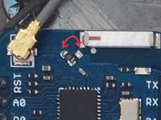
The resistor needs to be turned 90° from the pad near the rectangular ceramic antenna to the one near the antenna connector like this…

image

Pete.

1 Like

Thank you for the summary, well done.

I have tinkered with Uno board a few years back, watching LEDs blink, added the DHT22 and imagining the possibilities and then having the board sit in my desk a few years. Recently, and very randomly I stumbled upon Blynk and bought myself a NodeMCU board and found that my imaginations could probably become reality with this board(s).

I love your example of the Wemos pro w/ external antenna, very neat & tidy. How did you secure the board to the box?

Thanks, glad people are finding it, and then finding it useful.

The Wemos, relay and protocol board all plug into a 3-way base, which has mounting holes in it. I used some nylon bolts and glued their heads to the box with epoxy adhesive, and used threaded nylon standoffs instead of nuts to make it easier to tighten them with fingers.
The heads of the bolts are deep enough to keep the solder joints on the back of the 3-way base away from the metal box. By putting the bolts through the board first and screwing the ‘nuts’ on the other side the bolts are positioned correctly and can have the blob of epoxy applied to each one before offering the assembly up to the box. Much easier if the box is lying flat on the bench though.

Pete.

pictures Pete?

Hi @Costas, sorry for the delay. Arrived in Spain a couple of days ago and couldn’t remember where my box of M3 Nylon fixings were.

Apologies for the poor quality of the photos, taken on my phone.

The Wemos triple base I had to hand had quite long solder pins sticking out of the underside. Rather than trim them down I thought I’d demonstrate how to overcome that issue - handy for those of you that are somewhat challenged in the soldering department :grinning:

I used an M3 nylon bolt, plus a nut to give the extra clearance on the underside, then a hex spacer as the way to pinch the board down tight:

You could use nuts instead of the hex spacers, but then you’d need to use a nut driver or long nose pliers to tighten/loosen them. Much easier to use the hex spacers as nuts so that you can grip them with your fingers.

The Wemos double/triple bases have more clearance between the holes and the socket strips at the bottom (in the photo) than the top.

This makes it a bit trickier to tighten/loosen the hex spacers at the top, but it’s still do-able with the ones I have (bought on eBay from China).

On the bottom of the board is where the heads of the bolts are, and I put a blob of epoxy in the head of each bolt then turn it over and position it on whatever it is I’m mounting the base to:

Once the epoxy is set you can remove the hex spacers and the Wemos base, and add more epoxy if needed. But, if you’re happy with how it went together then just leave it as it is.

You don’t want bolts, or hex spacers, that are too long, as they will foul the Wemos or whatever accessory it is that you try to plug into the base.
I used M3 x 12mm nylon bolts and M3 x 8mm nylon hex spacers, plus M3 nylon nuts in this example.

Pete.

1 Like

nice topic !!
I bookmark it :wink:

2 Likes