Water level monitor + wemos + blynk

I came across this code on the internet. It was using MQTT, nodemcu to achieve water level monitor.

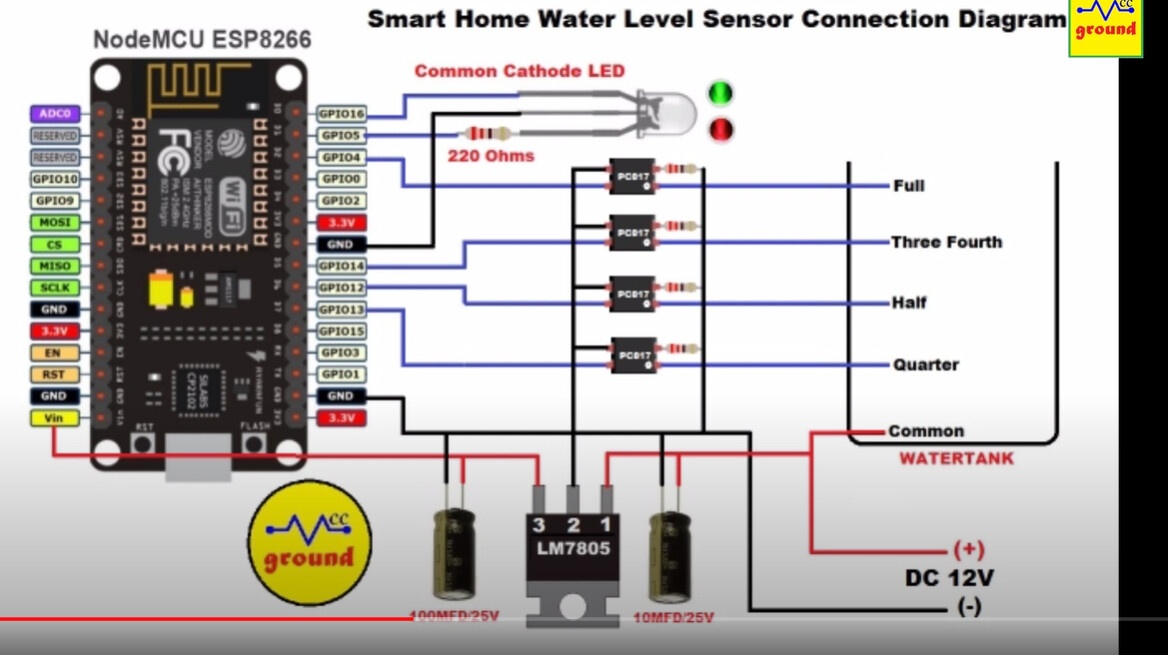
The hardware setup is as above and code is as found below


/********************* ADD FOLLOWING LIBRARIES TO ARDUINO IDE ****************************/
#include <ESP8266WiFi.h>
#include <PubSubClient.h>
#include <ESP8266mDNS.h>
#include <WiFiUdp.h>
#include <ArduinoOTA.h>
#include <ArduinoJson.h>

/******************* ADD YOUR WIFI and MQTT INFORMATION HERE ****************************/
#define wifi_ssid "your wifi ssid"
#define wifi_password "your wifi password"
#define mqtt_server "your mqtt server IP"
#define mqtt_user "your mqtt user name" 
#define mqtt_password "your mqtt password"
#define mqtt_port 1883
#define state_topic "watertank/level"

/**************************** FOR OVER THE AIR(OTA) UPDATES *****************************/
#define SENSORNAME "Watertank NodeMCU"
int OTAport = 8266;

/***************************** PIN DEFINATIONS *****************************************/
const int greenLED = D0;
const int redLED = D1;
const int quarter = D7;
const int half = D6;
const int threeFourth = D5;
const int full = D2;

int flag0=0;
int flag1=0; 
int flag2=0; 
int flag3=0; 
int flag4=0; 
int flag5=0;

String levelStatus;

char message_buff[100];
int calibrationTime = 0;
const int BUFFER_SIZE = 300;
#define MQTT_MAX_PACKET_SIZE 512

WiFiClient espClient;
PubSubClient client(espClient);

/********************************** START SETUP*****************************************/
void setup() {
  //Serial.begin(115200);               //Start serial monitor for debugging...
  pinMode(greenLED, OUTPUT);
  pinMode(redLED, OUTPUT);
  pinMode(quarter, INPUT_PULLUP);
  pinMode(half, INPUT_PULLUP);
  pinMode(threeFourth, INPUT_PULLUP);
  pinMode(full, INPUT_PULLUP);

  ArduinoOTA.setPort(OTAport);
  ArduinoOTA.setHostname(SENSORNAME);
  delay(10);
  Serial.println("Starting Node named " + String(SENSORNAME));

  setup_wifi();
  
  client.setServer(mqtt_server, mqtt_port);
  ArduinoOTA.onStart([]() {
  Serial.println("Starting");
  });
  ArduinoOTA.onEnd([]() {
  Serial.println("\nEnd");
  });
  ArduinoOTA.onProgress([](unsigned int progress, unsigned int total) {
  Serial.printf("Progress: %u%%\r", (progress / (total / 100)));
  });
  ArduinoOTA.onError([](ota_error_t error) {
  Serial.printf("Error[%u]: ", error);
    if (error == OTA_AUTH_ERROR) Serial.println("Auth Failed");
    else if (error == OTA_BEGIN_ERROR) Serial.println("Begin Failed");
    else if (error == OTA_CONNECT_ERROR) Serial.println("Connect Failed");
    else if (error == OTA_RECEIVE_ERROR) Serial.println("Receive Failed");
    else if (error == OTA_END_ERROR) Serial.println("End Failed");
  });
  ArduinoOTA.begin();
  Serial.println("Ready");
  Serial.print("IPess: ");
  Serial.println(WiFi.localIP());
  reconnect();
}

/********************************** SETUP WIFI *****************************************/
void setup_wifi() {

  delay(10);
  Serial.println();
  Serial.print("Connecting to ");
  Serial.println(wifi_ssid);

  WiFi.mode(WIFI_STA);
  WiFi.begin(wifi_ssid, wifi_password);

  while (WiFi.status() != WL_CONNECTED) {
  digitalWrite(greenLED, HIGH);
  digitalWrite(redLED, LOW);
  delay(500);
  digitalWrite(greenLED, LOW);
  digitalWrite(redLED, HIGH);
  delay(500);
  Serial.print(".");
  }

  Serial.println("");
  Serial.println("WiFi connected");
  Serial.println("IP address: ");
  Serial.println(WiFi.localIP());
  
  digitalWrite(greenLED, LOW);
  digitalWrite(redLED, LOW);
}

/********************************** START SEND STATE*****************************************/
void sendState() {
  StaticJsonBuffer<BUFFER_SIZE> jsonBuffer;

  JsonObject& root = jsonBuffer.createObject();

  root["waterlevel"] = (String)levelStatus;
  
  char buffer[root.measureLength() + 1];
  root.printTo(buffer, sizeof(buffer));

  Serial.println(buffer);
  client.publish(state_topic, buffer, true);
}

/********************************** START RECONNECT*****************************************/
void reconnect() {
  // Loop until we reconnect
  while (!client.connected()) {
    Serial.print("Attempting MQTT connection...");
    // Attempt to connect
    if (client.connect(SENSORNAME, mqtt_user, mqtt_password)) {
      Serial.println("connected");
    } else {
      Serial.print("failed, rc=");
      Serial.print(client.state());
      Serial.println(" try again in 5 seconds");
      // Wait 5 seconds before retrying
      delay(5000);
    }
  }
}

void loop() {
  ArduinoOTA.handle();
  if (!client.connected()) {
  flag0=0; flag1=0; flag2=0; flag3=0; flag4=0; flag5=0;
  digitalWrite(redLED, LOW);
  digitalWrite(greenLED, LOW);
  reconnect();
  }
  client.loop();

  if ((digitalRead(quarter)==HIGH) && (digitalRead(half)==HIGH) && (digitalRead(threeFourth)==HIGH) && (digitalRead(full)==HIGH)){      //if water level is below 25%
      if (flag0 == 0) {
      Serial.println("Tank is empty.....");
      digitalWrite(redLED, HIGH);
      digitalWrite(greenLED, LOW);
      levelStatus = "Empty";
      sendState();
      flag0=1; flag1=0; flag2=0; flag3=0; flag4=0; flag5=0;
  }}
  else if ((digitalRead(quarter)==LOW) && (digitalRead(half)==HIGH) && (digitalRead(threeFourth)==HIGH) && (digitalRead(full)==HIGH)){      //if water level is above 25%
      if (flag1 == 0) {
      digitalWrite(redLED, HIGH);
      digitalWrite(greenLED, LOW);
      Serial.println("Tank is quarter.....");
      levelStatus = "25% Filled";
      sendState();
      flag0=0; flag1=1; flag2=0; flag3=0; flag4=0; flag5=0;
  }}
  else if ((digitalRead(quarter)==LOW) && (digitalRead(half)==LOW) && (digitalRead(threeFourth)==HIGH) && (digitalRead(full)==HIGH)){     //if water level is above 50%
      if (flag2 == 0) {
      digitalWrite(redLED, HIGH);
      delay(100);
      digitalWrite(greenLED, HIGH);
      Serial.println("Tank is 50%.....");
      levelStatus = "Half Filled";
      sendState();
      flag0=0; flag1=0; flag2=1; flag3=0; flag4=0; flag5=0;
  }}
  else if ((digitalRead(quarter)==LOW) && (digitalRead(half)==LOW) && (digitalRead(threeFourth)==LOW) && (digitalRead(full)==HIGH)){     //if water level is above 75%
      if (flag3 == 0) {
      digitalWrite(redLED, LOW);
      digitalWrite(greenLED, HIGH);
      Serial.println("Tank is 75%.....");
      levelStatus = "75% Filled";
      sendState();
      flag0=0; flag1=0; flag2=0; flag3=1; flag4=0; flag5=0;
  }}
  else if ((digitalRead(quarter)==LOW) && (digitalRead(half)==LOW) && (digitalRead(threeFourth)==LOW) && (digitalRead(full)==LOW)){     //if water tank is Full
      if (flag4 == 0) {
      digitalWrite(redLED, LOW);
      digitalWrite(greenLED, LOW);
      Serial.println("Tank is full.....");
      levelStatus = "Full";
      sendState();
      //client.publish(tankState, "Full");  //publish the current state to MQTT
      flag0=0; flag1=0; flag2=0; flag3=0; flag4=1; flag5=0;
  }}
  else { Serial.println("Error.....");
      if (flag5 == 0) {
      levelStatus = "Sensor Cable Error...";
      sendState();
      flag0=0; flag1=0; flag2=0; flag3=0; flag4=0; flag5=1; } 
      else {
      digitalWrite(greenLED, HIGH);
      digitalWrite(redLED, LOW);
      delay(1000);
      digitalWrite(greenLED, LOW);
      digitalWrite(redLED, HIGH);
      delay(1000);
      digitalWrite(greenLED, LOW);
      digitalWrite(redLED, LOW);
  }}  delay(2000);
}

I have modified the above code to use with wemos d1 mini, it complies and upload to the wemos hardware, however the code is not quite doing anything.

Please help

#include <ESP8266mDNS.h> //ota
#include <WiFiUdp.h>  //ota
#include <ArduinoOTA.h> //ota

#include <Blynk.h>
#define BLYNK_PRINT Serial
#include <BlynkSimpleEsp8266.h>
BlynkTimer timer;


char auth[] = "xxxxx";

const int quarter = 0;  //d3 = 0
const int half = 13; //   d7=13
const int threeFourth = 14;  //d5=14
const int full = 5;  //gd1=5

int flag0=0;  //below 25%
int flag1=0; //above 25%
int flag2=0; //above 50%
int flag3=0; //above 75%
int flag4=0; //at 100%
int flag5=0; //sensor error??

void setup()
{
  Serial.begin(9600);
  Blynk.begin(auth, "xxxxx", "xxxxx");
 // pinMode(doorPin, INPUT);
  pinMode(quarter, INPUT);
  pinMode(half, INPUT);
  pinMode(threeFourth, INPUT);
  pinMode(full, INPUT_PULLUP);
  
  timer.setInterval(1000L, buttonLedWidget);
  }
 

void buttonLedWidget()
{
  
 if ((digitalRead(quarter)==HIGH) && (digitalRead(half)==HIGH) && (digitalRead(threeFourth)==HIGH) && (digitalRead(full)==HIGH)){      //if water level is below 25%
      if (flag0 == 0) {
      Serial.println("Tank is empty.....");
            flag0=1; flag1=0; flag2=0; flag3=0; flag4=0; flag5=0;
      Blynk.notify("water is below 25%");
  }}
  else if ((digitalRead(quarter)==LOW) && (digitalRead(half)==HIGH) && (digitalRead(threeFourth)==HIGH) && (digitalRead(full)==HIGH)){      //if water level is above 25%
      if (flag1 == 0) {
      Serial.println("Tank is quarter.....");
     flag0=0; flag1=1; flag2=0; flag3=0; flag4=0; flag5=0;
      Blynk.notify("water is quarter full");
  }}
  else if ((digitalRead(quarter)==LOW) && (digitalRead(half)==LOW) && (digitalRead(threeFourth)==HIGH) && (digitalRead(full)==HIGH)){     //if water level is above 50%
      if (flag2 == 0) {
      Serial.println("Tank is 50%.....");
      flag0=0; flag1=0; flag2=1; flag3=0; flag4=0; flag5=0;
      Blynk.notify("water is half full");
  }}
  else if ((digitalRead(quarter)==LOW) && (digitalRead(half)==LOW) && (digitalRead(threeFourth)==LOW) && (digitalRead(full)==HIGH)){     //if water level is above 75%
      if (flag3 == 0) {
      Serial.println("Tank is 75%.....");
     flag0=0; flag1=0; flag2=0; flag3=1; flag4=0; flag5=0;
      Blynk.notify("water is three quarters full");
  }}
  else if ((digitalRead(quarter)==LOW) && (digitalRead(half)==LOW) && (digitalRead(threeFourth)==LOW) && (digitalRead(full)==LOW)){     //if water tank is Full
      if (flag4 == 0) {
      Serial.println("Tank is full.....");
     flag0=0; flag1=0; flag2=0; flag3=0; flag4=1; flag5=0;
      Blynk.notify("water is 100% FULL");
  }}
  
}


void loop()
{
  Blynk.run();
  timer.run();
}


Maybe start by giving us a few clues?

Pete.

it would first print jibberish like this
8EpȠ0RJY⸮0`Ck⸮
then it will print
Tank is empty…

and thats it

The jiberish is the output from the Wemos at startup. If you set your serial monitor to 74880 and use the same baud rate in your code then the messages from your Wemos will be legible, along with your debug output.

Pete.

Okay done. after doing that I am only getting the tank is empty…

when any of of four sensors touch the water nothing happens in the serial monitor

For debugging modify your code to Serial.print() the state of the flags for every sensor state.

Also replace the senors with switches to eliminate any issue with the tank/water/common path etc.

Simplify the build and code until it works, then slowly add complexity.

billd

I replicated your circuit with switches and it is now working, this is clunky code with lost of Serial print debug, you can tidy it up.

It successfully measured the levels, connected to Blynk, and notified when levels changed.

#define BLYNK_PRINT Serial
#include <BlynkSimpleEsp8266.h>
#include <SimpleTimer.h>
BlynkTimer timer;


char auth[] = "nnn";

const int quarter = 4;  //d2 = 4
const int half = 13; //   d7=13
const int threeFourth = 14;  //d5=14
const int full = 5;  //d1=5

int flag0=0;  //below 25%
int flag1=0; //above 25%
int flag2=0; //above 50%
int flag3=0; //above 75%
int flag4=0; //at 100%
int flag5=0; //sensor error??

void setup()
{
  Serial.begin(9600);
  Blynk.begin(auth, "nnn", "nnn");
 // pinMode(doorPin, INPUT);
  pinMode(quarter, INPUT_PULLUP);
  pinMode(half, INPUT_PULLUP);
  pinMode(threeFourth, INPUT_PULLUP);
  pinMode(full, INPUT_PULLUP);
  
  timer.setInterval(1000L, buttonLedWidget);
  }
 

void buttonLedWidget()
{

Serial.print(digitalRead(quarter)); Serial.print(digitalRead(half)); Serial.print(digitalRead(threeFourth)); Serial.print(digitalRead(full));
Serial.println();


 if ((digitalRead(quarter)==HIGH) && (digitalRead(half)==HIGH) && (digitalRead(threeFourth)==HIGH) && (digitalRead(full)==HIGH)){      //if water level is below 25%
      if (flag0 == 0) {
      
      Serial.println("Tank is empty.....");
            flag0=1; flag1=0; flag2=0; flag3=0; flag4=0; flag5=0;
      
      Blynk.notify("water is below 25%");
  }}
  else if ((digitalRead(quarter)==LOW) && (digitalRead(half)==HIGH) && (digitalRead(threeFourth)==HIGH) && (digitalRead(full)==HIGH)){      //if water level is above 25%
      if (flag1 == 0) {
      Serial.println("Tank is quarter.....");
     flag0=0; flag1=1; flag2=0; flag3=0; flag4=0; flag5=0;
      Blynk.notify("water is quarter full");
  }}
  else if ((digitalRead(quarter)==LOW) && (digitalRead(half)==LOW) && (digitalRead(threeFourth)==HIGH) && (digitalRead(full)==HIGH)){     //if water level is above 50%
      if (flag2 == 0) {
      Serial.println("Tank is 50%.....");
      flag0=0; flag1=0; flag2=1; flag3=0; flag4=0; flag5=0;
      Blynk.notify("water is half full");
  }}
  else if ((digitalRead(quarter)==LOW) && (digitalRead(half)==LOW) && (digitalRead(threeFourth)==LOW) && (digitalRead(full)==HIGH)){     //if water level is above 75%
      if (flag3 == 0) {
      Serial.println("Tank is 75%.....");
     flag0=0; flag1=0; flag2=0; flag3=1; flag4=0; flag5=0;
      Blynk.notify("water is three quarters full");
  }}
  else if ((digitalRead(quarter)==LOW) && (digitalRead(half)==LOW) && (digitalRead(threeFourth)==LOW) && (digitalRead(full)==LOW)){     //if water tank is Full
      if (flag4 == 0) {
      Serial.println("Tank is full.....");
     flag0=0; flag1=0; flag2=0; flag3=0; flag4=1; flag5=0;
      Blynk.notify("water is 100% FULL");
  }}
Serial.print("flag0 = "); Serial.println(flag0);
Serial.print("flag1 = "); Serial.println(flag1);
Serial.print("flag2 = "); Serial.println(flag2);
Serial.print("flag3 = "); Serial.println(flag3);
Serial.print("flag4 = "); Serial.println(flag4);
Serial.print("flag5 = "); Serial.println(flag5); 
}


void loop()
{
  Blynk.run();
  timer.run();
}

cul
billd

To be honest, the approach of applying 12v + to an electrode in the tank and expecting logic level outputs to be available at the sensors placed at various heights in the tank is a bit weird.
Certainly the way that it’s shown in the diagram, with the “common” connection at the bottom of the tank isn’t going to work well, as the resistance of the water will mean that the voltage on the “full” electrode will be much lower than the “quarter” electrode.

Even if it was a metal tank, I’m sceptical about whether or not the voltages appearing at the output electrodes would be sufficient to turn on the PC817 opto isolators.

And, even if this worked, it would be making the GPIO inputs HIGH when the water level was above the output sensors, which makes no sense when the GPIOs are being initialised with an INPUT_PULLUP modifier (at least in the original code, but only for the full pin on the modified code).

Also, passing a current through water will result in some electro-plating action to take place, unless it’s distilled water, which will probably affect the reliability of the sensors over time.

This is why people use non-contact sensors such as ultrasonic measuring devices, or throw-in level sensors that measure the air pressure in a sealed tube.

Pete.

PS:

Avoid GPIO 0 (D3), it will cause erratic results. I changed it to GPIO 4 (D2)

Put #define BLYNK_PRINT Serial as the first line of code, it will show your Blynk connection info in serial monitor.

Define all your pins as INPUT_PULLUP

cul
billd

Actually, this is how this one is working:
https://www.kemo-electronic.de/en/House/Garden/M167N-Level-Indicator-for-Water-Tanks.php

I’ve been using this one for the past 5 years in a underground 30.000 gallons concrete reservoir before I heard about Blynk.

It actually is still operational, but I now just use Blynk with a ultrasonic sensor. :laughing:

The principal is similar, but I think there are a few important differences…

  1. power is only applied to the submerged contacts when a reading is going to be taken
  2. the circuitry is measuring the voltage received by each electrode and presumably has its own internal threshold for what it considers to be a reading which relates to a “submerged” reading. That’s a very different scenario to exciting an opto coupler to the point where it turns on (HIGH)

And that’s the way that I’d go too!

Pete.

thanks for all the response guys. Really appreciate it.

I have uploaded the code provided by Bill_Donnelly. It is working to an extent. Let me explain.

I have copy paste the serial monitor print below. After it connects to blynk…the first thing it will do is display the flag values 1111 and then displays tank is empty and then continue reading 1111 until the one of the sensor is activated

on touching the quarter full sensor to water it will read 0111 and then read tank is quarter and then continue printing 0111…up until here it is good.

on touching the half full sensor to water it will read 1011 and continue printing 1011…it will NOT print tank is half full

similarly on touching the 3/4 full sensor to water it will read 1101 and continue printing 1101…it will NOT print tank is 3/4 full

and lastly on touching the full sensor to water it will read 1110 and continue printing 1110…but it will NOT print tank is full.

then it reset back to 1111 after all the sensor are removed from the water.

2638] Connecting to blynk-cloud.com:80
[2869] Ready (ping: 85ms).
1111
Tank is empty.....
1111
1111
0111
Tank is quarter.....
0111
0111
0111
1011
1011
1011
1011
1011
1011
1011
1011
1101
1101
1101
1101
1101
1101
1101
1101
1110
1110
1110
1110
1110
1110
1111
Tank is empty.....
1111
1111
1111

Bill’s code includes these lines of code:

and that would not produce an output like this:

so I think you’ve modified the code in some way. As a result, it’s impossible to say where the issue lies.

By the way, your Blynk notifications will flood the Blynk server with data because you are limited to one notification every 5 seconds and you are sending one every second.
I’d suggest that you remove the notification code during testing, and add-it back in in a more appropriate way at a later date.

Pete.

yup you are right. i forgot to submit code.

Yes I will change blynk notification to every 5 seconds.


#define BLYNK_PRINT Serial
#include <BlynkSimpleEsp8266.h>
//#include <SimpleTimer.h>
BlynkTimer timer;


char auth[] = "nnn";

const int quarter = 12;  //d6 = 12 
const int half = 13; //   
const int threeFourth = 14;  //d5=14
const int full = 5;  //d1=5

int flag0=0;  //below 25%
int flag1=0; //above 25%
int flag2=0; //above 50%
int flag3=0; //above 75%
int flag4=0; //at 100%
int flag5=0; //sensor error??

void setup()
{
  Serial.begin(9600);
  Blynk.begin(auth, "nnn", "nnn");
  pinMode(quarter, INPUT_PULLUP);
  pinMode(half, INPUT_PULLUP);
  pinMode(threeFourth, INPUT_PULLUP);
  pinMode(full, INPUT_PULLUP);
  
  timer.setInterval(1000L, buttonLedWidget);
  }
 

void buttonLedWidget()
{

Serial.print(digitalRead(quarter)); Serial.print(digitalRead(half)); Serial.print(digitalRead(threeFourth)); Serial.print(digitalRead(full));
Serial.println();


 if ((digitalRead(quarter)==HIGH) && (digitalRead(half)==HIGH) && (digitalRead(threeFourth)==HIGH) && (digitalRead(full)==HIGH)){      //if water level is below 25%
      if (flag0 == 0) {
      
      Serial.println("Tank is empty.....");
            flag0=1; flag1=0; flag2=0; flag3=0; flag4=0; flag5=0;
            Blynk.notify("water is below 25%");
  }}
  else if ((digitalRead(quarter)==LOW) && (digitalRead(half)==HIGH) && (digitalRead(threeFourth)==HIGH) && (digitalRead(full)==HIGH)){      //if water level is above 25%
      if (flag1 == 0) {
      Serial.println("Tank is quarter.....");
     flag0=0; flag1=1; flag2=0; flag3=0; flag4=0; flag5=0;
      Blynk.notify("water is quarter full");
  }}
  else if ((digitalRead(quarter)==LOW) && (digitalRead(half)==LOW) && (digitalRead(threeFourth)==HIGH) && (digitalRead(full)==HIGH)){     //if water level is above 50%
      if (flag2 == 0) {
      Serial.println("Tank is 50%.....");
      flag0=0; flag1=0; flag2=1; flag3=0; flag4=0; flag5=0;
      Blynk.notify("water is half full");
  }}
  else if ((digitalRead(quarter)==LOW) && (digitalRead(half)==LOW) && (digitalRead(threeFourth)==LOW) && (digitalRead(full)==HIGH)){     //if water level is above 75%
      if (flag3 == 0) {
      Serial.println("Tank is 75%.....");
     flag0=0; flag1=0; flag2=0; flag3=1; flag4=0; flag5=0;
      Blynk.notify("water is three quarters full");
  }}
  else if ((digitalRead(quarter)==LOW) && (digitalRead(half)==LOW) && (digitalRead(threeFourth)==LOW) && (digitalRead(full)==LOW)){     //if water tank is Full
      if (flag4 == 0) {
      Serial.println("Tank is full.....");
     flag0=0; flag1=0; flag2=0; flag3=0; flag4=1; flag5=0;
      Blynk.notify("water is 100% FULL");
  }}
//Serial.print("flag0 = "); Serial.println(flag0);
//Serial.print("flag1 = "); Serial.println(flag1);
//Serial.print("flag2 = "); Serial.println(flag2);
//Serial.print("flag3 = "); Serial.println(flag3);
//Serial.print("flag4 = "); Serial.println(flag4);
//Serial.print("flag5 = "); Serial.println(flag5); 
}


void loop()
{
  Blynk.run();
  timer.run();
}


``

So why don’t you want to see the flag values in your serial monitor?

Pete.

I enabled the flag values and copy pasted the serial output below.

similar result like before. The empty as well as quarter output works good however not the rest.

2639] Connecting to blynk-cloud.com:80
[2866] Ready (ping: 81ms).
1111
Tank is empty.....
flag0 = 1
flag1 = 0
flag2 = 0
flag3 = 0
flag4 = 0
flag5 = 0
1111
flag0 = 1
flag1 = 0
flag2 = 0
flag3 = 0
flag4 = 0
flag5 = 0
0111
Tank is quarter.....
flag0 = 0
flag1 = 1
flag2 = 0
flag3 = 0
flag4 = 0
flag5 = 0
0111
flag0 = 0
flag1 = 1
flag2 = 0
flag3 = 0
flag4 = 0
flag5 = 0
1011
flag0 = 0
flag1 = 1
flag2 = 0
flag3 = 0
flag4 = 0
flag5 = 0
1011
flag0 = 0
flag1 = 1
flag2 = 0
flag3 = 0
flag4 = 0
flag5 = 0
1101
flag0 = 0
flag1 = 1
flag2 = 0
flag3 = 0
flag4 = 0
flag5 = 0
1101
flag0 = 0
flag1 = 1
flag2 = 0
flag3 = 0
flag4 = 0
flag5 = 0
1110
flag0 = 0
flag1 = 1
flag2 = 0
flag3 = 0
flag4 = 0
flag5 = 0
1110
flag0 = 0
flag1 = 1
flag2 = 0
flag3 = 0
flag4 = 0
flag5 = 0
1111
Tank is empty.....
flag0 = 1
flag1 = 0
flag2 = 0
flag3 = 0
flag4 = 0
flag5 = 0

And from that you can see that your flags aren’t being updated for anything other than empty and 25%

Pete.

Yes I noticed. Do you think the wemos pin that I am using, are wrong or something along those lines??

No, the pin values are changing.
It’s a problem with the nested if else statements.
Adding some serial print statements in there may help you figure out the issue.

Personally, I don’t see the point in these if/else statements. Only one can be true, so they ought to be simple if statements in my opinion.

Pete.