You would think this to be easy, but for a noob like me this has become mission impossible for the last 2 weeks. I rarely ask for help because I find I learn way more by pushing myself…however, I am getting to the point of giving up on Blynk as something so seemingly simply has become this monumental task.
The setup: I have a simple water flow sensor that is a digital 0 when off and when water flows through it, it becomes a digital on / 1. I am using an esp8266 and am only using digital pin 0. All I wanted to be able to do is use a super graph widget to display a “1/on” when the sensor is on and “0/off” when no water is flowing. Since by default digital input pins are high I need to REVERSE THE LOGIC. Currently everything works in the fashion that when the sensor is off, the graph shows “on/high/1” and when the sensor is on, it shows the opposite. You can see in my code where I tried this and am failing somewhere.
In my desperate attempt to fix this I went down another rabbit hole that’s got me really pissed off. In human terms all I wanted to do was debug the code and tell the soc to “please show me the status of virtual pin 1” aka serial print the the serial monitor V1. OMG if this isint the hardest thing in the world, I don’t know what is. It shouldn’t be this complicated to perform either one of these tasks, but for new people such as myself, this is well…end of line.
/*
The below code produces the following serial monitor output

Connecting to FlufferNet
[3250] Connected to WiFi
[3250] IP: 192.168.10.107
[3250]
___  __          __
/ _ )/ /_ _____  / /__
/ _  / / // / _ \/  '_/
/____/_/\_, /_//_/_/\_\
/___/ v0.4.10 on ESP8266

[5001] Connecting to blynk-cloud.com:8442
[5283] Ready (ping: 1ms).
*/

#define BLYNK_PRINT Serial


// Include the following libraries
#include <ESP8266WiFi.h>
#include <BlynkSimpleEsp8266.h>


//Blynk and Wifi Credentials
char auth[] = "af8d835xxxxxxxxxxxxxxxxxxxxxxxxxxxxx";   // Auth Token in the Blynk App.
char ssid[] = "FlufferNet";   // Your WiFi sid name. Set password to "" for open networks.
char pass[] = "dkNY%xxxxxxxxxxxxxxx";// Your WiFi password. Set password to "" for open networks.


int sensorData; //define an interger variable called sensorData


BlynkTimer timer; // Announcing the blynk timer


//Creating a function that will be performed in intervals.
void myTimerEvent()
{
  sensorData = digitalRead(0);    //Read the value of digital pin 0
  Blynk.virtualWrite(V4, sensorData); //Send the value of sensorData to Virtual pin 4
  Serial.print("Pin 0 value = "); //Print "Pin 0 value ="
  Serial.println(sensorData); //Print the value thats in the sensorData variable
  Serial.println(param.asInt(4)); //print the value of virtual pin 4
 }


//invert the digital pin logic.  By default pin 0 is high, so on the graph it looks like its always on.  This will make it
//so that default is off and when the flow sensor spins up, it looks like its "on" to the graph
BLYNK_WRITE(V4)
{
int pinValue = param.asInt();
if (param.asInt() == 0)
{
digitalWrite(0, LOW);
}
else
{
digitalWrite(0, HIGH);
}
}


void setup()
{
  Serial.begin(9600); //Turn on the serial monitor
  Blynk.begin(auth, ssid, pass);  //Initiate blynk wifi with blynk server


 // Setup pin 0 to be an input pin
  pinMode(0, INPUT);
  digitalWrite(0, HIGH);

// Declare that our function myTimerEvent() should run every 1000 milliseconds, which is 1 second.
  timer.setInterval(1000L, myTimerEvent);
}


void loop()
{
  Blynk.run();  //The basic line to run all blynk commands
  timer.run(); // Initiates the Blynk Timer
}
Why BLYNK_WRITE(V4) subrutine contain digitalWrite? What you are tryin to is read hardware pin and write virtual pin. Try to remove digitalWrite commands there. And also on myTimerEvent() try
sensorData = !digitalRead(0);
void myTimerEvent()
{
  sensorData = !digitalRead(0);    //Read the value of digital pin 0
  Blynk.virtualWrite(V4, sensorData); //Send the value of sensorData to Virtual pin 4
  Serial.print("Pin 0 value = "); //Print "Pin 0 value ="
  Serial.println(sensorData); //Print the value thats in the sensorData variable
  Serial.println(param.asInt(4)); //print the value of virtual pin 4
 }
Like I said everything works fine, I just need to reverse the pin logic. The second part of displaying the virtual pin information in the serial monitor is just icing on the cake. Being as that I barely understand code, like…AT ALL lol, I am amazing at myself for getting this far from scratch. I just dont understand what you are trying to do…and thats my goal - I need to understand. The help is much appreciated.
#define BLYNK_PRINT Serial

// Include the following libraries
#include <ESP8266WiFi.h>
#include <BlynkSimpleEsp8266.h>

//Blynk and Wifi Credentials
char auth[] = "af8d835xxxxxxxxxxxxxxxxxxxxxxxxxxxxx";  // Auth Token in the Blynk App.
char ssid[] = "FlufferNet";                            // Your WiFi sid name. Set password to "" for open networks.
char pass[] = "dkNY%xxxxxxxxxxxxxxx";                  // Your WiFi password. Set password to "" for open networks.

int sensorData;                                        // define an interger variable called sensorData

BlynkTimer timer;                                      // Announcing the blynk timer

void myTimerEvent()
{
  sensorData = !digitalRead(0);                        // Read the value of digital pin 0
  Blynk.virtualWrite(V4, sensorData);                  // Send the value of sensorData to Virtual pin 4
  Serial.print("Pin 0 value = ");                      // Print "Pin 0 value ="
  Serial.println(sensorData);                          // Print the value thats in the sensorData variable
}

void setup()
{
  Serial.begin(9600);
  Blynk.begin(auth, ssid, pass);                       // Initiate blynk wifi with blynk server

  timer.setInterval(2000L, myTimerEvent);
}

void loop()
{
  Blynk.run();                                         // The basic line to run all blynk commands
  timer.run();                                         // Initiates the Blynk Timer
}
please notice the ! before the digitalRead(0);, this is the “reverse logic” what you need. (it reverses the boolean value)
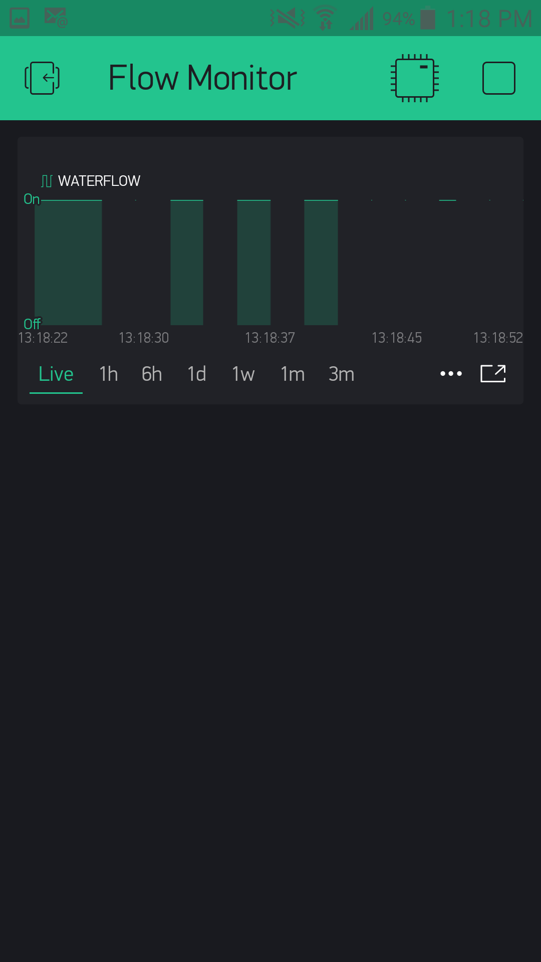
YES and NO (ugggg) the output is below so it appears the logic reversal works!! but for some reason the graph is…sporadic, and not reflecting what the true pin state now is.
Pin 0 value = 0
Pin 0 value = 0
Pin 0 value = 0
Pin 0 value = 0
Pin 0 value = 0
Pin 0 value = 0
Pin 0 value = 0
Pin 0 value = 0
Pin 0 value = 0
Pin 0 value = 0
Pin 0 value = 0
Pin 0 value = 0
Pin 0 value = 0
Pin 0 value = 0
Pin 0 value = 0
Pin 0 value = 0
Pin 0 value = 0
Pin 0 value = 0
Pin 0 value = 0
Pin 0 value = 0
*I shorted pin 0 to ground here
Pin 0 value = 1
Pin 0 value = 1
Pin 0 value = 1
Pin 0 value = 1
Pin 0 value = 1
Pin 0 value = 1
Pin 0 value = 1
Pin 0 value = 1
Pin 0 value = 1
Pin 0 value = 1
Pin 0 value = 1
Pin 0 value = 1
Pin 0 value = 1
Pin 0 value = 1
Pin 0 value = 1
Pin 0 value = 1
Pin 0 value = 1
Pin 0 value = 1
Pin 0 value = 1
Pin 0 value = 1
Pin 0 value = 1
Pin 0 value = 1
Pin 0 value = 1
Pin 0 value = 1
Pin 0 value = 1
Pin 0 value = 1
Pin 0 value = 1
Pin 0 value = 1
yeah, i think i know the reason. it is because of some wired functionality in the super chart. it was already discussed somewhere, but i can’t find now. the thing is, try to set up super chart like this:
yeah mine looked exactly the same but 0,0,1 . 0,0,2 now gives my nada. So its a bug huh? Glad I didnt spend any money on Blynk with it being this buggy and im this new with something so insanely simple.
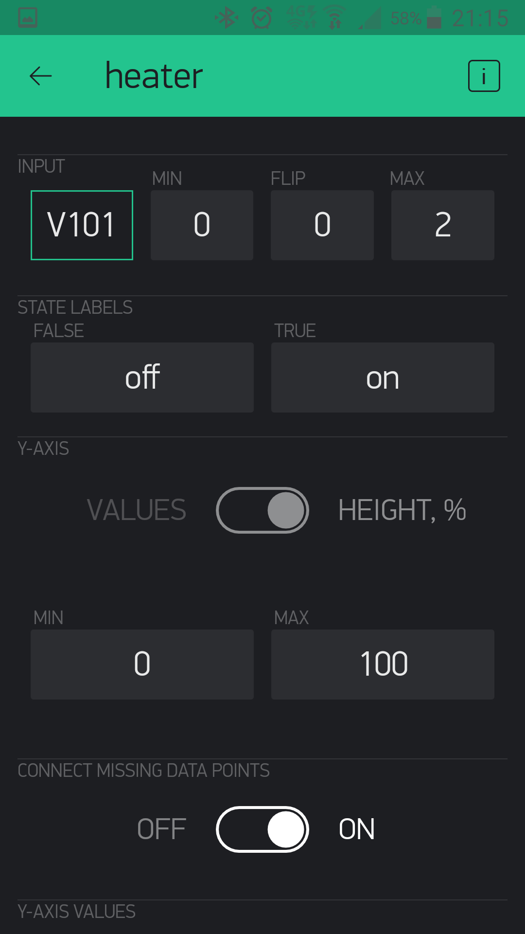
what is important the min, flip, max values and the button set to height %, and the connect missing data point to “on”. also, try to switch between live and 1h display. it should work in the end, lots of other people is using.
actually i do not think it is a bug, just some wired logic for the digital data… @BlynkAndroidDev?
tried all that. If you keep it on 1 hour…than go back to live. The live view acts like its correct and has been “on” the entire time until 2 seconds pass and then it updates back to off. Its a bug.
got it to work with 0,0,1 and connect data points. thanks so much for the help!!! Now I just have to go through your code and try to understand what the hell you did.
actually nothing special. the only interesting part for you is the “!”, which reverses the value of a bool. you could even further minimise the code if you remove the serial prints:
#include <ESP8266WiFi.h>
#include <BlynkSimpleEsp8266.h>

char auth[] = "af8d835xxxxxxxxxxxxxxxxxxxxxxxxxxxxx";  // Auth Token in the Blynk App.
char ssid[] = "FlufferNet";                            // Set password to "" for open networks.
char pass[] = "dkNY%xxxxxxxxxxxxxxx";                  // Set password to "" for open networks.

BlynkTimer timer;

void myTimerEvent()
{
  Blynk.virtualWrite(V4, !digitalRead(0));             // Send the reversed value of pin 0 to Virtual pin 4
}

void setup()
{
  Blynk.begin(auth, ssid, pass);
  timer.setInterval(2000L, myTimerEvent);
}

void loop()
{
  Blynk.run();                                         // The basic line to run all blynk commands
  timer.run();                                         // Initiates the Blynk Timer
}