Hello How Are You
My Friends
I have one solar system at.my home I want to monitoring.my solar and power consumption
Is it possible may I use two PZEM-004T
One for solar other for output
Yes, it is!!!
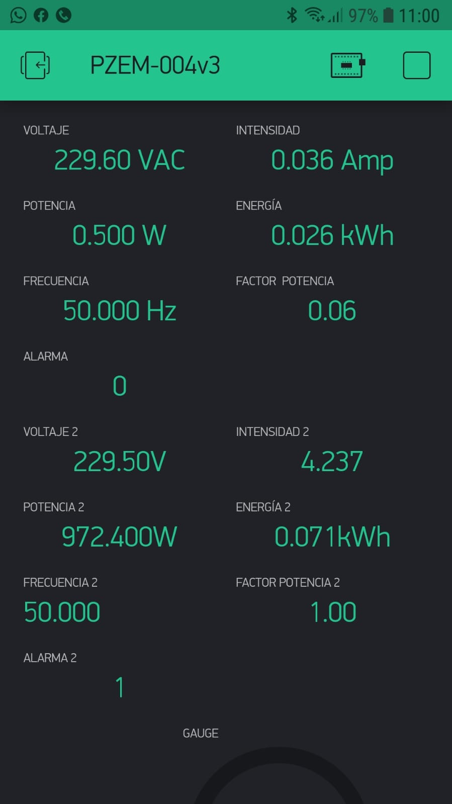
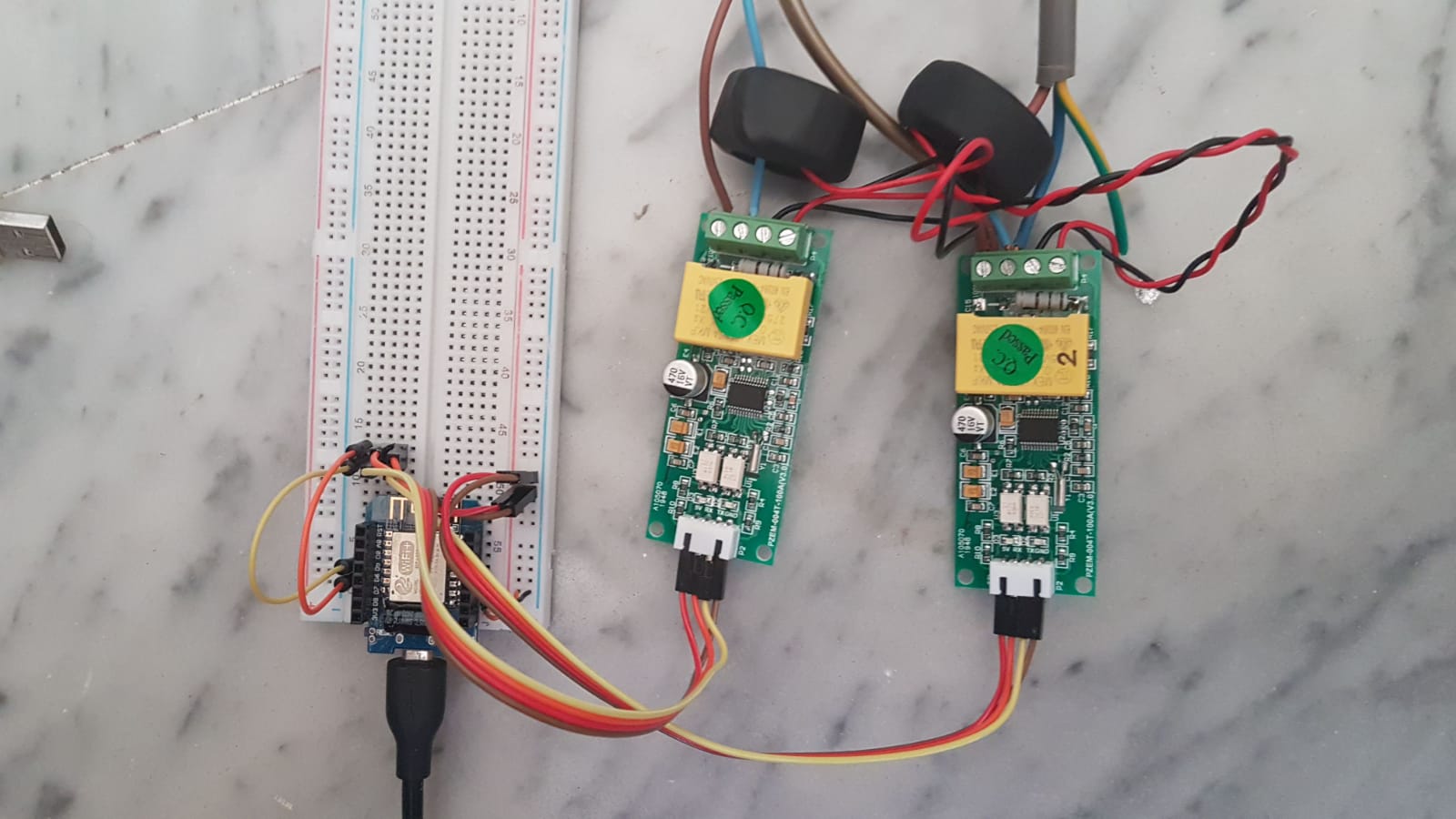
PZEM 1 was measuring only it’s own consumption, PZEM 2 was also measuring a 1 kW resistive load (heater)
Both PZEMs connected in parallel to the software serial-Modbus bus.
The Modbus address of one of them was changed from 1 to 2 using the Windows software provided by the manufacturer (Peacefair).
Here is the modified sketch (prepared also for a third PZEM):
#include <BlynkSimpleEsp8266.h>
//#include <SimpleTimer.h> // desactivada complia sin tocar nada más, pero añado mas adelante "BlynkTimer timer"
#include <ModbusMaster.h>
#include <ESP8266WiFi.h>
#include "settingsPZEM.h"

#include <SoftwareSerial.h>  //  ( NODEMCU ESP8266 )
SoftwareSerial pzem(D5,D6);  // (RX,TX) connect to TX,RX of PZEM for NodeMCU
//SoftwareSerial pzem(D7,D8);  // (RX,TX) connect to TX,RX of PZEM
#include <ModbusMaster.h>

// instantiate ModbusMaster objectS
ModbusMaster node1;
ModbusMaster node2; //quitar comentario para 2 PZEMs
// ModbusMaster node3; //quitar comentario para 3 PZEMs


// SimpleTimer timer; // sustituida por la siguiente para usar BlynkTimer en lugar de Simpletimer según lo indicado en foro
BlynkTimer timer;

//WiFi data
char ssid[] = "********";        //WiFi Credential
char pass[] = "*******";    //WiFi Password
// Datos servidor
char server[] = "192.168.1.***";  //Blynk local server IP address
int port = 8080;                  //Blynk local port
#define USE_LOCAL_SERVER       //Use local Blynk Server - comment-out if use Blynk hosted cloud service
#define AUTH "***************" //PZEM-004v3 Auth code
int timerTask1;
double U_PR, I_PR,  P_PR,  PPR, PR_F, PR_PF; bool PR_alarm;
double U_PR_2, I_PR_2,  P_PR_2,  PPR_2, PR_F_2, PR_PF_2; bool PR_alarm_2; //quitar comentario para 2 PZEMs
// double U_PR_3, I_PR_3,  P_PR_3,  PPR_3, PR_F_3, PR_PF_3; bool PR_alarm_3; //quitar comentario para 3 PZEMs
uint8_t result; // uint16_t data[6]; //parece que data[6] no se usa!- quitado sin efecto


void setup(){

  Serial.begin(74880); Serial.println("Start serial");

  // codigo para verificar arranque con un parpadeo del LED
    pinMode(LED_BUILTIN, OUTPUT);
    for (int i = 0; i < 6 ; i++){
    Serial.println("LED on");
    digitalWrite(LED_BUILTIN, LOW);
    delay(200);
    digitalWrite(LED_BUILTIN, HIGH);
    Serial.println("LED off");
    delay(200);
    }
  // fin código LED en arranque

  pzem.begin(9600); Serial.println("Start PZEM serial");

  node1.begin(1, pzem);  Serial.println("Start PZEM"); // 1 = ID MODBUS, pzem=puerto serie soft definido arriba
  node2.begin(2, pzem);  Serial.println("Start PZEM 2"); // 2 = ID MODBUS quitar comentario para 2 PZEMs sobre el mismo puerto serie soft
  //node3.begin(3, pzem);  Serial.println("Start PZEM 3"); // 3 = ID MODBUS quitar comentario para 3 PZEMs sobre el mismo puerto serie soft

  WiFi.mode(WIFI_STA);
  #if defined(USE_LOCAL_SERVER)
    Serial.println("Conectando a WiFi");
    WiFi.begin(ssid, pass);
    Serial.println("Conectando a servidor local");
    Blynk.config(AUTH, server, port);
  #else
    Serial.println("Conectando a WiFi y servidor Blynk");
    Blynk.begin(AUTH, ssid, pass);
  #endif
  while (Blynk.connect() == false) {}
  Serial.println("Conectado a servidor");
  ArduinoOTA.setHostname(OTA_HOSTNAME);
  ArduinoOTA.begin();

//  timerTask1 = timer.setInterval(1000, updateBlynk);

}

void updateBlynk() {
  Blynk.virtualWrite(vPIN_VOLTAGE,               U_PR);
  Blynk.virtualWrite(vPIN_CURRENT_USAGE,         I_PR);
  Blynk.virtualWrite(vPIN_ACTIVE_POWER,          P_PR);
  Blynk.virtualWrite(vPIN_ACTIVE_ENERGY,         PPR);
  Blynk.virtualWrite(vPIN_FREQUENCY,             PR_F);
  Blynk.virtualWrite(vPIN_POWER_FACTOR,          PR_PF);
  Blynk.virtualWrite(vPIN_OVER_POWER_ALARM,      PR_alarm);

  //quitar comentario para 2 PZEMs

  Blynk.virtualWrite(vPIN_VOLTAGE_2,             U_PR_2);
  Blynk.virtualWrite(vPIN_CURRENT_USAGE_2,       I_PR_2);
  Blynk.virtualWrite(vPIN_ACTIVE_POWER_2,        P_PR_2);
  Blynk.virtualWrite(vPIN_ACTIVE_ENERGY_2,       PPR_2);
  Blynk.virtualWrite(vPIN_FREQUENCY_2,           PR_F_2);
  Blynk.virtualWrite(vPIN_POWER_FACTOR_2,        PR_PF_2);
  Blynk.virtualWrite(vPIN_OVER_POWER_ALARM_2,    PR_alarm_2);

  //quitar comentario para 3 PZEMs
  /*
  Blynk.virtualWrite(vPIN_VOLTAGE_3,             U_PR_3);
  Blynk.virtualWrite(vPIN_CURRENT_USAGE_3,       I_PR_3);
  Blynk.virtualWrite(vPIN_ACTIVE_POWER_3,        P_PR_3);
  Blynk.virtualWrite(vPIN_ACTIVE_ENERGY_3,       PPR_3);
  Blynk.virtualWrite(vPIN_FREQUENCY_3,           PR_F_3);
  Blynk.virtualWrite(vPIN_POWER_FACTOR_3,        PR_PF_3);
  Blynk.virtualWrite(vPIN_OVER_POWER_ALARM_3,    PR_alarm_3);
  */
}

void loop(){
Blynk.run();
//ArduinoOTA.handle();
//timer.run();

// nodo1
result = node1.readInputRegisters(0x0000, 10);
if (result == node1.ku8MBSuccess)  {
  U_PR      = (node1.getResponseBuffer(0x00)/10.0f);
  I_PR      = (node1.getResponseBuffer(0x01)/1000.000f);
  P_PR      = (node1.getResponseBuffer(0x03)/10.0f);
  PPR       = (node1.getResponseBuffer(0x05)/1000.0f);
  PR_F      = (node1.getResponseBuffer(0x07)/10.0f);
  PR_PF     = (node1.getResponseBuffer(0x08)/100.0f);
  PR_alarm  = (node1.getResponseBuffer(0x09));

  Serial.println("nodo 1 OK - LED on");
  digitalWrite(LED_BUILTIN, LOW);
  Serial.print("U_PR:       "); Serial.println(U_PR);     // V
  Serial.print("I_PR:       "); Serial.println(I_PR,3);   //  A
  Serial.print("P_PR:       "); Serial.println(P_PR);     //  W
  Serial.print("PPR:        "); Serial.println(PPR,3);    // kWh
  Serial.print("PR_F:       "); Serial.println(PR_F);     // Hz
  Serial.print("PR_PF:      "); Serial.println(PR_PF);    // FP
  Serial.print("PR_alarm:   "); Serial.println(PR_alarm); // Alarm
  Serial.println("====================================================");
  delay(200);
  Serial.println("nodo 1 - LED off");
  digitalWrite(LED_BUILTIN, HIGH);
  }
delay(200);

// nodo2
// quitar comentario para 2 PZEMs
result = node2.readInputRegisters(0x0000, 10);
if (result == node2.ku8MBSuccess)  {
  U_PR_2       = (node2.getResponseBuffer(0x00)/10.0f);
  I_PR_2       = (node2.getResponseBuffer(0x01)/1000.000f);
  P_PR_2       = (node2.getResponseBuffer(0x03)/10.0f);
  PPR_2        = (node2.getResponseBuffer(0x05)/1000.0f);
  PR_F_2       = (node2.getResponseBuffer(0x07)/10.0f);
  PR_PF_2      = (node2.getResponseBuffer(0x08)/100.0f);
  PR_alarm_2   = (node2.getResponseBuffer(0x09));

  Serial.println("nodo 2 OK - LED on");
  digitalWrite(LED_BUILTIN, LOW);
  Serial.print("U_PR_2:     "); Serial.println(U_PR_2);     // V
  Serial.print("I_PR_2:     "); Serial.println(I_PR_2,3);   // A
  Serial.print("P_PR_2:     "); Serial.println(P_PR_2);     // W
  Serial.print("PPR_2:      "); Serial.println(PPR_2,3);    // kWh
  Serial.print("PR_F_2:     "); Serial.println(PR_F_2);     // Hz
  Serial.print("PR_PF_2:    "); Serial.println(PR_PF_2);    // FP
  Serial.print("PR_alarm_2: "); Serial.println(PR_alarm_2); // Alarm
  Serial.println("====================================================");
  delay(200);
  Serial.println("nodo 2 - LED off");
  digitalWrite(LED_BUILTIN, HIGH);
  }
delay(200);
// nodo3
// quitar comentario para 3 PZEMs
/*
updateBlynk();
delay(500);
result = node3.readInputRegisters(0x0000, 10);
if (result == node3.ku8MBSuccess)  {
  U_PR_3     = (node3.getResponseBuffer(0x00)/10.0f);
  I_PR_3     = (node3.getResponseBuffer(0x01)/1000.000f);
  P_PR_3     = (node3.getResponseBuffer(0x03)/10.0f);
  PPR_3      = (node3.getResponseBuffer(0x05)/1000.0f);
  PR_F_3     = (node3.getResponseBuffer(0x07)/10.0f);
  PR_PF_3    = (node3.getResponseBuffer(0x08)/100.0f);
  PR_alarm_3 = (node3.getResponseBuffer(0x09));

  Serial.println("nodo 3 OK - LED on");
  digitalWrite(LED_BUILTIN, LOW);
  Serial.print("U_PR_3:     "); Serial.println(U_PR_3);     // V
  Serial.print("I_PR_3:     "); Serial.println(I_PR_3,3);   // A
  Serial.print("P_PR_3:     "); Serial.println(P_PR_3);     // W
  Serial.print("PPR_3:      "); Serial.println(PPR_3,3);    // kWh
  Serial.print("PR_F_3:     "); Serial.println(PR_F_3);     // Hz
  Serial.print("PR_PF_3:    "); Serial.println(PR_PF_3);    // FP
  Serial.print("PR_alarm_3: "); Serial.println(PR_alarm_3); // Alarm
  Serial.println("====================================================");
  delay(200);
  Serial.println("nodo 2 - LED off");
  digitalWrite(LED_BUILTIN, HIGH);
  }
delay(200);
*/
updateBlynk();
}
And the modified settingsPZEM.h
//#include <wifi_credentials.h>
// Remove below 2 lines when use Blynk hosted server,
//#define USE_LOCAL_SERVER
//#define SERVER IPAddress(192,168,1,***)
/*
  Over The Air Hostname
*/
#define OTA_HOSTNAME                    "PZEM-004v3"
/*
   Virtual Pins - Base
*/
#define vPIN_VOLTAGE                V0
#define vPIN_CURRENT_USAGE          V1
#define vPIN_ACTIVE_POWER           V2
#define vPIN_ACTIVE_ENERGY          V3
#define vPIN_FREQUENCY              V4
#define vPIN_POWER_FACTOR           V5
#define vPIN_OVER_POWER_ALARM       V6

//quitar comentario para 2 PZEMs
//Fase 2
#define vPIN_VOLTAGE_2              V7
#define vPIN_CURRENT_USAGE_2        V8
#define vPIN_ACTIVE_POWER_2         V9
#define vPIN_ACTIVE_ENERGY_2        V10
#define vPIN_FREQUENCY_2            V11
#define vPIN_POWER_FACTOR_2         V12
#define vPIN_OVER_POWER_ALARM_2     V13

//quitar comentario para 3 PZEMs
//Fase 3
/*
#define vPIN_VOLTAGE_3              V14
#define vPIN_CURRENT_USAGE_3        V15
#define vPIN_ACTIVE_POWER_3         V16
#define vPIN_ACTIVE_ENERGY_3        V17
#define vPIN_FREQUENCY_3            V18
#define vPIN_POWER_FACTOR_3         V19
#define vPIN_OVER_POWER_ALARM_3     V20
*/


/*
   Debug. Change to 0 when you are finished debugging.
*/
const int debug             =           1;
/*

*/
1 Like
As you can see, the sketch in my previous post is not very efficient, as it needs to repeat several blocks of code with slight changes.
With a little help from my son, who suggested using an array of modbusmaster instances (we weren’t sure it was going to work, but it did!), I rewrote the code which is now shorter, with a more “elegant” approach to using several sensors, very easy to “escalate” in case more sensors are added.
I also simplified Key’s code (the base for this one, which had some remains of former experiments, vars, and libraries that weren’t needed) and also eliminated the need for “settingsPZEM.h”.
// #include <ArduinoOTA.h> //not used
#include <BlynkSimpleEsp8266.h>
#include <ModbusMaster.h>
#include <ESP8266WiFi.h>

#include <SoftwareSerial.h>
SoftwareSerial pzem(D5,D6);   // (RX,TX) connect to TX,RX of PZEM for NodeMCU
//SoftwareSerial pzem(D7,D8); // (RX,TX) connect to TX,RX of PZEM
#include <ModbusMaster.h>

// instantiate ModbusMaster objects
ModbusMaster node[3];

BlynkTimer timer;

//WiFi data
char ssid[] = "*********";        //WiFi Credential
char pass[] = "**********";    //WiFi Password

// Server data
char server[] = "192.168.1.XXX";  //Blynk local server IP address
int port = 8080;                  //Blynk local port
#define USE_LOCAL_SERVER          //Use local Blynk Server - comment-out if use Blynk hosted cloud service

#define AUTH "******************************" //PZEM-004v3 Auth code for 192.168.1.XXX:9443 (gmail)

// #define OTA_HOSTNAME "PZEM-004v3" // Brought from settingsPZEM.h, not needed


// Vars for reading PZEM's output
float U_PR[3], I_PR[3],  P_PR[3],  E_PR[3], F_PR[3], PF_PR[3]; bool AL_PR[3];
uint8_t result;

void setup(){

  // Flash LED on start
    pinMode(LED_BUILTIN, OUTPUT);
    for (int i = 0; i < 6 ; i++){
      Serial.println("LED on");
      digitalWrite(LED_BUILTIN, LOW);
      delay(200);
      digitalWrite(LED_BUILTIN, HIGH);
      Serial.println("LED off");
      delay(200);
      }
  // End LED flash

  //Initialize serial ports and Modbus nodes
  Serial.begin(74880); Serial.println("Start serial");
  pzem.begin(9600); Serial.println("Start PZEM serial");
  node[0].begin(1, pzem);  Serial.println("Start PZEM 1"); // 1 = ID MODBUS, pzem = soft serial port previously defined
  node[1].begin(2, pzem);  Serial.println("Start PZEM 2"); // 2 = ID MODBUS
  node[2].begin(3, pzem);  Serial.println("Start PZEM 3"); // 3 = ID MODBUS

  //Wifi and server connect
  WiFi.mode(WIFI_STA);
  #if defined(USE_LOCAL_SERVER)
    Serial.println("Connecting to WiFi");
    WiFi.begin(ssid, pass);
    Serial.println("Connecting local Blync server");
    Blynk.config(AUTH, server, port);
  #else
    Serial.println("Connecting to WiFi and Blynk");
    Blynk.begin(AUTH, ssid, pass);
  #endif
  while (Blynk.connect() == false) {}
  Serial.println("Connected!");

//  ArduinoOTA.setHostname(OTA_HOSTNAME);
//  ArduinoOTA.begin();
//  timerTask1 = timer.setInterval(1000, updateBlynk);

} //end Setup

void updateBlynk() { // Write values to Blynk's virtual pins
for (int i=0; i<3; i++){
  //Write to Blynk virtual pins
  Blynk.virtualWrite(7*i,   U_PR[i]);     // Write voltage to V0, V7, V14
  Blynk.virtualWrite(7*i+1, I_PR[i]);     // Write current to V1, V8, V15
  Blynk.virtualWrite(7*i+2, P_PR[i]);     // Write active power to V2, V9, V16
  Blynk.virtualWrite(7*i+3, E_PR[i]);      // Write active energy to V3, V10, V17
  Blynk.virtualWrite(7*i+4, F_PR[i]);     // Write frequency to V4, V11, V18
  Blynk.virtualWrite(7*i+5, PF_PR[i]);    // Write power factor to V5, V12, V19
  Blynk.virtualWrite(7*i+6, AL_PR[i]); // Write alarm status to V6, V13, V20
  }
} //End updateBlynk()


void loop(){
Serial.println("Starting loop");
Blynk.run();
//ArduinoOTA.handle();

for (int i=0; i<3; i++){
  result = node[i].readInputRegisters(0x0000, 10); // leer 10 registros comenzando en el 0
  if (result == node[i].ku8MBSuccess)  {

    U_PR[i]      = (node[i].getResponseBuffer(0x00)/10.0f);
    I_PR[i]      = ((node[i].getResponseBuffer(0x01) + (node[i].getResponseBuffer(0x02)*65532))/1000.000f);
    P_PR[i]      = ((node[i].getResponseBuffer(0x03) + (node[i].getResponseBuffer(0x04)*65532))/10.0f);
    E_PR[i]      = ((node[i].getResponseBuffer(0x05) + (node[i].getResponseBuffer(0x06)*65532))/1000.0f);
    F_PR[i]      = (node[i].getResponseBuffer(0x07)/10.0f);
    PF_PR[i]     = (node[i].getResponseBuffer(0x08)/100.0f);
    AL_PR[i]     = (node[i].getResponseBuffer(0x09));

    Serial.print("Node ");  Serial.print(i+1); Serial.println(" OK    LED on");
    digitalWrite(LED_BUILTIN, LOW);
    Serial.print("Voltage      ");  Serial.print(U_PR[i]);     Serial.println(" V");  // V
    Serial.print("Current      ");  Serial.print(I_PR[i],3);   Serial.println(" A");  // A
    Serial.print("Active power ");  Serial.print(P_PR[i]);     Serial.println(" W");  // W
    Serial.print("Energy       ");  Serial.print(E_PR[i],3);   Serial.println(" kWh");// kWh
    Serial.print("Frequency    ");  Serial.print(F_PR[i]);     Serial.println(" Hz"); // Hz
    Serial.print("Power factor ");  Serial.print(PF_PR[i]);    Serial.println();      // FP
    Serial.print("Alarm        ");  Serial.print(AL_PR[i]);    Serial.println();      // Alarm
    delay(200);
    Serial.print("Node ");  Serial.print(i+1); Serial.println("       LED off");
    digitalWrite(LED_BUILTIN, HIGH);
    Serial.println("====================================================");
    }
  else{
    U_PR[i]       = 0;
    I_PR[i]       = 0;
    P_PR[i]       = 0;
    // E_PR[i]       = 0; //If PZEM cannot be read (lost of power), last energy would be better aproximation than zero
    F_PR[i]       = 0;
    PF_PR[i]      = 0;
    AL_PR[i]      = 0;

    Serial.print("Node ");  Serial.print(i+1); Serial.println(" ERROR");
    Serial.println("====================================================");
    }
  delay(200);
  }

updateBlynk();

}
That’s a nasty looking void loop and will almost certainly lead to Blynk issues during long term running.
You should use a BlynkTimer to call a function that takes the readings from your sensors on a regular basis.
Have a read of this:
Pete.
Thanks for the information!
That was going to be the next step; I’m new to this, I had already read that it wasn’t a good idea to add delays and “overcharge” the main loop but, as I had started using Key’s code, I just followed that way at the beginning. Now I have to learn how to use timers.
I’ve had the code running for a long time without issues but, as I have to add more functions, I should do the things properly to avoid future problems.
BTW, I’m also considering switching to PZEM-004T-v30 library, instead of ModbusMaster. I’ve tried the array approach with it and also seems to work
[EDIT] It was easier than I thought!! Just bringing the contents of the loop to a new function and calling it with the timer:
#include <BlynkSimpleEsp8266.h>
#include <ModbusMaster.h>
#include <ESP8266WiFi.h>

#include <SoftwareSerial.h>
SoftwareSerial pzem(D5,D6);   // (RX,TX) connect to TX,RX of PZEM for NodeMCU
#include <ModbusMaster.h>

// instantiate ModbusMaster objects
ModbusMaster node[3];

BlynkTimer timer;

//WiFi data
char ssid[] = "*********";        //WiFi Credential
char pass[] = "**********";    //WiFi Password

// Server data
char server[] = "192.168.1.XXX";  //Blynk local server IP address
int port = 8080;                  //Blynk local port
#define USE_LOCAL_SERVER          //Use local Blynk Server - comment-out if use Blynk hosted cloud service
#define AUTH "**************************" //PZEM-004v3 Auth code for 192.168.1.XXX:9443

// Vars for reading PZEM data
float U_PR[3], I_PR[3],  P_PR[3],  E_PR[3], F_PR[3], PF_PR[3]; bool AL_PR[3];
uint8_t result;

void setup(){

  // Flash LED on start
    pinMode(LED_BUILTIN, OUTPUT);
    for (int i = 0; i < 6 ; i++){
      Serial.println("LED on");
      digitalWrite(LED_BUILTIN, LOW);
      delay(200);
      digitalWrite(LED_BUILTIN, HIGH);
      Serial.println("LED off");
      delay(200);
      }
  // End LED flash

  //Initialize serial ports and Modbus nodes
  Serial.begin(74880); Serial.println("Start serial");
  pzem.begin(9600); Serial.println("Start PZEM serial");
  node[0].begin(1, pzem);  Serial.println("Start PZEM 1"); // 1 = ID MODBUS, pzem = soft serial port previously defined
  node[1].begin(2, pzem);  Serial.println("Start PZEM 2"); // 2 = ID MODBUS
  node[2].begin(3, pzem);  Serial.println("Start PZEM 3"); // 3 = ID MODBUS

  //Wifi and server connect
  WiFi.mode(WIFI_STA);
  #if defined(USE_LOCAL_SERVER)
    Serial.println("Connecting to WiFi");
    WiFi.begin(ssid, pass);
    Serial.println("Connecting local Blync server");
    Blynk.config(AUTH, server, port);
  #else
    Serial.println("Connecting to WiFi and Blynk");
    Blynk.begin(AUTH, ssid, pass);
  #endif
  while (Blynk.connect() == false) {}
  Serial.println("Connected!");

timer.setInterval(1000, updateData);

} //end Setup

void updateData() {  // Read values from sensors
for (int i=0; i<3; i++){
  result = node[i].readInputRegisters(0x0000, 10); // Read 10 registers starting on 0
  if (result == node[i].ku8MBSuccess)  {
    U_PR[i]      = (node[i].getResponseBuffer(0x00)/10.0f);
    I_PR[i]      = ((node[i].getResponseBuffer(0x01) + (node[i].getResponseBuffer(0x02)*65532))/1000.000f);
    P_PR[i]      = ((node[i].getResponseBuffer(0x03) + (node[i].getResponseBuffer(0x04)*65532))/10.0f);
    E_PR[i]      = ((node[i].getResponseBuffer(0x05) + (node[i].getResponseBuffer(0x06)*65532))/1000.0f);
    F_PR[i]      = (node[i].getResponseBuffer(0x07)/10.0f);
    PF_PR[i]     = (node[i].getResponseBuffer(0x08)/100.0f);
    AL_PR[i]     = (node[i].getResponseBuffer(0x09));

    Serial.print("Node ");  Serial.print(i+1); Serial.println(" OK    LED on");
    digitalWrite(LED_BUILTIN, LOW);
    Serial.print("Voltage      ");  Serial.print(U_PR[i]);     Serial.println(" V");  // V
    Serial.print("Current      ");  Serial.print(I_PR[i],3);   Serial.println(" A");  // A
    Serial.print("Active power ");  Serial.print(P_PR[i]);     Serial.println(" W");  // W
    Serial.print("Energy       ");  Serial.print(E_PR[i],3);   Serial.println(" kWh");// kWh
    Serial.print("Frequency    ");  Serial.print(F_PR[i]);     Serial.println(" Hz"); // Hz
    Serial.print("Power factor ");  Serial.print(PF_PR[i]);    Serial.println();      // FP
    Serial.print("Alarm        ");  Serial.print(AL_PR[i]);    Serial.println();      // Alarm
    Serial.print("Node ");  Serial.print(i+1); Serial.println("       LED off");
    digitalWrite(LED_BUILTIN, HIGH);
    Serial.println("====================================================");
    }
  else{
    U_PR[i]       = 0;
    I_PR[i]       = 0;
    P_PR[i]       = 0;
    // E_PR[i]       = 0; //If PZEM cannot be read (lost of power), last energy would be better aproximation than zero
    F_PR[i]       = 0;
    PF_PR[i]      = 0;
    AL_PR[i]      = 0;

    Serial.print("Node ");  Serial.print(i+1); Serial.println(" ERROR");
    Serial.println("====================================================");
    }
  }

updateBlynk();
}

void updateBlynk() { // Write values to Blynk's virtual pins
for (int i=0; i<3; i++){
  //Write to Blynk virtual pins
  Blynk.virtualWrite(7*i,   U_PR[i]);     // Write voltage to V0, V7, V14
  Blynk.virtualWrite(7*i+1, I_PR[i]);     // Write current to V1, V8, V15
  Blynk.virtualWrite(7*i+2, P_PR[i]);     // Write active power to V2, V9, V16
  Blynk.virtualWrite(7*i+3, E_PR[i]);      // Write active energy to V3, V10, V17
  Blynk.virtualWrite(7*i+4, F_PR[i]);     // Write frequency to V4, V11, V18
  Blynk.virtualWrite(7*i+5, PF_PR[i]);    // Write power factor to V5, V12, V19
  Blynk.virtualWrite(7*i+6, AL_PR[i]); // Write alarm status to V6, V13, V20
  }
} //End updateBlynk()


void loop(){
  Blynk.run();
  timer.run();
}
Tested and seem to work OK. Thanks again for the advice!
The array approach is a good one, especially when dealing with small numbers of sensors.
An alternative is to pass a parameter to a function which takes the readings from the specified sensor and writes them to Blynk.
Pete.
Thanks!
I already edited the previous post to add the modified code using a timer instead of including it in the loop. I hope it’s more orthodox now!
I investigated the option of passing the parameter (better option, I think) instead of the array approach, but I’m not sure if it’s possible the way the ModbusMaster and PZEM004Tv30 libraries are written and called.
Apparently, it’s not possible with PZEM004Tv30, so I suggested a change to admit the slave address as a parameter, instead of creating a different instance for each slave, but I’m not sure if it’s difficult to implement (I tried to study the source code myself but was beyond my capabilities  ).
).
Regarding ModbusMaster, somebody asked about several slaves here, and was suggested to create several instances instead of using parameters; later, apparently, somebody modified the code to do it, but I think this mod is not in the main branch, as it’s dated in 2016 and the mod in 2018.
Obviously a library that allows one instance for multiple sensors, and parameterised library function calls would be the nicest solution. However, that wasn’t what I was meaning when I said about calling a function with a parameter.
In the absence of the perfect solution, my approach would be to create a function that accepts a parameter.
Like this bit of pseudocode…
void readPZEM( int pzem_id )
{
  result = node[pzem_id].readInputRegisters(0x0000, 10); // Read 10 registers starting on 0
  if (result == node[pzem_id].ku8MBSuccess)  {

  // code in here to write result to Blynk.
}
You can then either call this via a for loop, or with one timer for each pzem sensor.
Pete.
If you have pzem004t V3 module, you can use this library https://github.com/mandulaj/PZEM-004T-v30
Getting values is easy like this : float volt = pzem.voltage();
@ishdemon @Morgan_Flint has already said:
and that as part of exploring this option he’s said in post #9 the he’s suggested an enhancement to the library.
Pete.
Thank you all for your replies. I still got caught up with kids and work during this pandemic. Let me dive into your codings.