That’s not a response I’ve ever heard from Alexa. “Not responding” is the usual response.
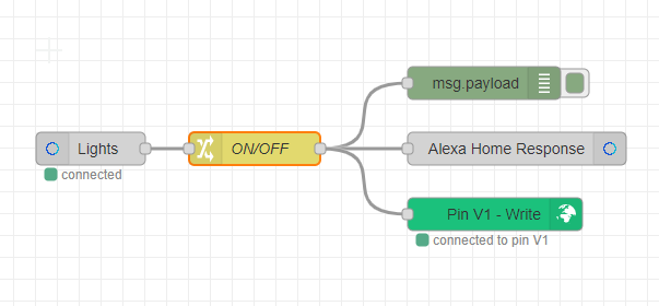
You don’t need to use the Alexa response node when you’re just turning devices on or off, it’s only needed when you want Alexa to say a value obtained from the flow, such as the temperature. Without the response node Alexa will say “Okay”, assuming Brief Mode isn’t enabled in the Alexa app - in which case you’ll just get a short sound.
If you do use the Alexa response node then you have to feed it data in the correct format, with the msg.extra element correctly populated.
I think you may also run in to the issue that Blynk won’t trigger an action from a Write command that comes from the same Auth code, so you may need to use the Bridge widget.
As I’ve said before, I don’t run any Blynk code on my devices, I just run MQTT code and let Node-Red handle the rest, so I don’t have these issues.
Thanks alot. I read it 3 times and also many examples over the internet and i can’t manage to work. I don’t know what i must do to control the relay state using the MQTT, my lack of knowledge of this is evident. Maybe im to stupid to put it to work lol. I will leave the idea of control it by Alexa and stick it to the Blynk app.
In simple terms, the device (lets say a NodeMCU) can publish data to MQTT topics and also subscribe to MQTT topics.
The publish side of things is very similar to doing a Blynk.virtualWrite.
The subscribe side of things is a bit more complex, but fairly simple to implement when you understand what to do. Your device “watches’ a topic by subscribing to it. When a message arrives on a subscribed topic the MQTT callback function is triggered and you can then take some action.
This is similar to the BLYNK_WRITE(vPin) callbacks in Blynk which are triggered when a virtual pin value changes.
The code example I linked to provides two parameters that relate to the received message - the topic (because you could be subscribes to multiple topics) and the value that was published on that topic.
It really helps to use MQTT Explorer to check that your device is publishing data and to ensure that you’re publishing data to the correct topics.
All of this is covered in the example I linked to and plugging your WiFi credentials and MQTT server data into the code example should allow you to turn the NodeMCU’s built-in LED (GPIO2) on and off by publishing ‘ON’ or ‘OFF’ to the topic ‘My_MQTT_Test/NodeMCU_Test_Device/LED’
Ok, but in my sketch, this specific case, i must subscribe and also publish or just subscribe to a topic and make the rest on node Red?
Im sorry for the dumb questions, but At this time, my problem is understandig the workflow of this thing.
To turn on a light (or LED for that matter) you need to subscribe to a topic then send a command to that topic from Node-Red.
The NodeMCU code needs to turn the light/LED on or off when the message is received from Node-Red as in my example.
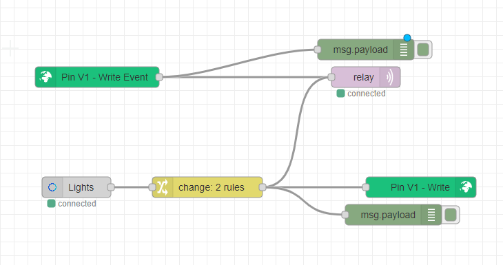
In Node-Red you’ll have incoming triggers from widgets on the Blynk app, Alexa nodes and any other sources (an object node within the flow for example) and an output that sends the MQTT message to the NodeMCU.
I like to publish messages from my NodeMCU so that I can see what’s happening easily, without having to connect it to a serial monitor.
MQTT has something called a ‘last will and testament’ which is way to do something when the device disappears off the network. That’s what the ‘alive’ and ‘dead’ stuff does in the sketch I linked to.
Me standard sketch also publishes lots of data at startup, such as compile date, file name, IP address etc.
I also publish other data, usually every 5 seconds to give info on RSSI, uptime, number of WiFi snd MQTT reconnections etc. etc.
This isn’t necessary, but often useful.
I also like to publish a ‘response’ message when an MQTT message has been received snd actioned by my device. For example, if an ‘ON’ message wad received telling the device to turn the LED on, I’d send another message back, maybe on a LED/Status topic confirming that the LED is on. I’ll often use this to operate an LED widget in the app which confirms that the command has been actioned.
Ok, Pete, i made i final experience before i go sleep and get things working more or less. Here it goes. Sketck was copied and little worked from well knowned forum and i used your flow example. But some problems/questions have to be cleared:
1 - Sketch is working, but dunno, i think it has to be polished, alot. It looks strange, but is working.
2 - I used true/false in change node because TurnOnRequest/TurnOffRequest does not work
3 - Alexa, turns on and off, but… instead on saying “Ok” it says after a while "Device is not working, check connections bla bla, but it works despite her answer. What am i missing?
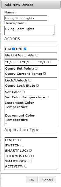
Don’t forget that of you make any changes to the Alexa Home device settings, you should do an “Alexa, Discover new devices”. She’ll tell you that no new devices were found, but the attributes/capabilities of the existing devices will have been updated.
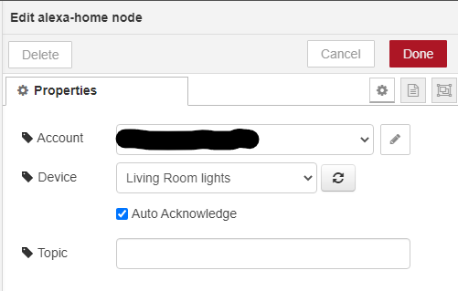
Also, do you have a tick in the “Auto Acknowledge” check box? …
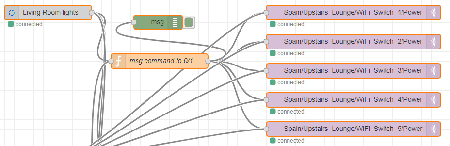
(Ignore the fact that there’s no Blynk node in this part of the flow, Blynk is updated elsewhere in Node-Red in this case).
The “msg.command to 0/1” function contains this code…
var OnOff;

if (msg.command==='TurnOnRequest')
{
    OnOff="1";
}

if (msg.command==='TurnOffRequest')
{
        OnOff="0";
}

return {'payload': OnOff};
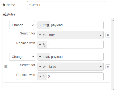
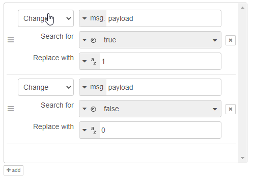
which is really just the same as using a Change node with two rules, but as you can see, the TurnOnRequest and TurnOffRequest commands, are received on msg.command not on msg.payload which appears to be what you were trying to do.
It was the check box… I thought that it should be unchecked… Now is working Ok. I will try to polish the sketch. I dont like how it is despite working.
I will try adapt the one you did, but is not working on my ESP32. I think is a library issue
The Auto Acknowledge checkbox should always be checked, unless you’re using the Alexa Response node. You only use the response node if you want Alexa to respond with a value from a variable within the flow, such as temperature.
ESP32 requires the WIFI.h Library instead of ESP8266WiFi.h and I think the connection process might need tweaking a little (or you could use the one from your sketch).
Yes… I knew that. I already changed connection process and now remain only two problems.
First, mqtt_client_id = String(ESP.getChipId()); does not work. maybe its a chip issue
Second, timer.setInterval(5000, MQTT_Heartbeat); the timer also gives an error. i think is a library compatibility thing. Im using for now the Blynk library timer. Works same way
Yes, I think that’s a function that’s only supported with the ESP8266.
mqtt_client_id Is used to identify the device when the MQTT connection is made, and this needs to be unique for each device. The ChipId was a neat way to do this, but the Mqqt_client_id could be anything you want it to be.
To do that you need to include some of the Blynk library.
My guess is that you don’t have SimpleTimer library installed, and it’s trying to use the SimpleTimer files that it finds in the Blynk library at compile time, which gives an error.
I have SimpleTimer library installed. v1.0.0 from arduino ide library manager. Nevertheless, if i switch simpleTimer from BlynkTimer command and use the BlynkSimpleESP32 library, code works. If i stick to SimpleTimer library, it gives the timer.SetInterval error.
My question is, is there other SimpleTimer library?
no matching function for call to ‘SimpleTimer::setInterval(long int, void (&)())’
I found the problem. I was using the wrong SimpleTimer library. I was using the one of Arduino IDE list. I’ve installed now the Simple-Timer-library from GitHub and is working fine now