Three LEDs with Dirty Delay (ESP32)

So, I received my ESP32 recently and I wanted to show you guys how to set it up so you can actually use he very dirty Delay function without messing up the wonderful world of Blynk.

Note: this project is NOT affiliated with @Gunner his flashy light led blynky thing! :wink:

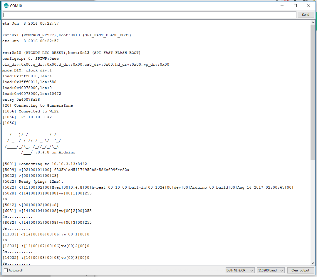
So, ESP32 has actually got two cores. If you setup the board in the IDE so you can program it, you can also address the two different cores and run your sketch in a multithreaded fashion. As demonstrated by the below code. It flashes three LEDā€™s on V1, V2 and V3 with a big dirty loop full of delays!

#define BLYNK_PRINT Serial

#include <Arduino.h> // This include is only needed if you build on PlatformIO
#include <WiFi.h>
#include <WiFiClient.h>
#include <BlynkSimpleEsp32.h>

char auth[] = "charstuff";

char ssid[] = "wifistuff";
char pass[] = "morewifistuff";

WidgetLED led1(V1);
WidgetLED led2(V2);
WidgetLED led3(V3);

// Dirty loop with delays, YUCK!
void loop1(void *pvParameters)
{
  while (1)
  {
    if (led1.getValue()) { led1.off();
    } else { led1.on(); }
    Serial.println("1s");
    delay(1000);

    if (led2.getValue()) { led2.off();
    } else { led2.on(); }
    Serial.println("2s");
    delay(2000);

    if (led3.getValue()) { led3.off();
    } else { led3.on(); }
    Serial.println("3s");
    delay(3000);
  }
}

// And running blynk stuff on other loop. Note the 1ms delay, this is need so the watchdog doesn't get confused
void loop2(void *pvParameters) {
  while (1) {
     Blynk.run();
     delay(1);
  }
}

void setup()
{
  Serial.begin(9600);

  Blynk.begin(auth, ssid, pass, "serverstuffhere or cloud", 8442);

  // Here we create what is normally a timer thing
  // Note the last argument, this is the Core of the ESP it will run on!
  xTaskCreatePinnedToCore(loop1, "loop1", 4096, NULL, 1, NULL, 0);
  xTaskCreatePinnedToCore(loop2, "loop2", 4096, NULL, 1, NULL, 1);
}

void loop()
{
// And an emtpy loop!
}

Enjoy!

7 Likes

very interesting. i didnā€™t know about this. where can i read more detailed docs about it?

Well, this is totally unsupported I think. The ESP32 is still in beta stage. Iā€™ve found the info https://github.com/copercini/esp32-iot-examples/blob/master/multiloop/multiloop.ino here and added Blynk in the loop, sort of speak ā€¦ :smiley:

3 Likes

but in the reality these 2 loops indeed run completely isolated? i mean no matter what is happening in loop1, loop2 can do blynk and wifi stuff?

that whould be a great help for time sensitive functions and stepper motor control for example!

Yes. They run on physically different CPU cores of the ESP32 because it has two Cores.

very cool! thanks for shareing :wink:

That is awesome!

One thing missing though, I havenā€™t got any Blynk debug output on the Serial port. So that would require some attention. Not sure why not. Other Serial output is fine.

Thatā€™s only because your rebel trio of LEDs is no match for the Blinky firepower of my fully operational battlestation of 72 LEDs :stuck_out_tongue:

However, it may have more practical applicationsā€¦ :blush:

That worked OK on Arduino IDEā€¦ perhaps a PlatformIO issue?

1 Like

On that ā€œspareā€ void loop, which will also run stuffā€¦ which core does it use?

That is user-specified, it seems! Last argument as per comment

  // Here we create what is normally a timer thing
  // Note the last argument, this is the Core of the ESP it will run on!
  xTaskCreatePinnedToCore(loop1, "loop1", 4096, NULL, 1, NULL, 0);
  xTaskCreatePinnedToCore(loop2, "loop2", 4096, NULL, 1, NULL, 1);
1 Like

I use CoolTerm for serial monitoring. Guess it could be me. Iā€™m just glad I can separate all the task for now. This opens up a whole new range of possibilities (mostly dirty programming, lol).

@Fettkeewl I guess then that since it is the ā€œdefaultā€ loop and otherwise unspecified, it probably runs on the default coreā€¦ 0? EDIT - Nope, Core 1, based on one of those documents @Lichtsignaal posted below.

I knew the ESP had dual cores, but I thought the 2nd one was dedicated to the WiFi interfaceā€¦ this calls for more investigationā€¦ Meanwhile I must rethink which ESP to put in my rover as this might greatly improve its functionality without a massive timer investment.

http://esp32.info/docs/esp_idf/html/db/da4/task_8h.html#adf67e7cd0bfd1eda9e8afd048206f7c2

More info here on the specific functions you can use with xTaskCreate stuff.

And even mroe here: ESP32: Running code on a specific core - techtutorialsx (this is a good one I think).

@Gunner I think it also depends on the Priority settings, from what I can gather when creating the task

3 Likes

A side question, did you try the ADC On esp32?

I just read that it has 2 ADCs supporting 9 channels each, I was wondering if that meant that
each ADC could handle 9 different adc readings in sequence?
Or is it limited to 1 channel per adc but you can choose which one?

No idea, havenā€™t ADC yet, but Iā€™ll try and see if I can add some analog stuff to it. If I can find some sensorsā€¦ lol.

-edit

If I look at the pictures it just has 9 analog ports, or so it sems.

Crap, it even has 10(!!!) integrated touch sensors. This means you can use a simple copperclad board to create a keypad for example :smiley:

Pretty cool ehā€¦ This will be a sweet Blynk board once all the teething issues are worked outā€¦ OTA, BLE, WiFi, Touch, Multiple UARTS, Dual Core, Fast, lots of IO, etc.

Unfortunately the latest Update IDF libs broke something in ArduinoOTAā€¦ so that doesnā€™t work, and I have no idea how to revert to the ā€œpriorā€ update :blush: So much new too fast.

EDIT - It has been fixed now :smiley: Now I just have to figure out how to get it to work more than onceā€¦ something is different in the required commands then with the ESP8266.

Looks fun :smile:
https://youtu.be/iusvNh6VfmE

ADC works here is demo:

1 Like