Well, as easy as:
pinMode (12, OUTPUT);
digitalWrite (12, HIGH);  //turns RLY ON
digitalWrite (12, LOW);  //turns RLY OFF
But then again: some conditions are needed here, or a Blynk Button (see example in sketch builder or at docs.blynk.cc)
Well, as easy as:
pinMode (12, OUTPUT);
digitalWrite (12, HIGH); //turns RLY ON
digitalWrite (12, LOW); //turns RLY OFF
But then again: some conditions are needed here, or a Blynk Button (see example in sketch builder or at docs.blynk.cc)
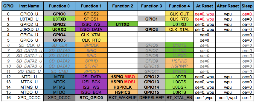
I indeed wasn’t aware of that table, but then again I also can’t read it, that is: I do not comprehend it. I recognize the GPIO’s and thats about it. But basically I only need to know:
main LED: pin 13 (blue in my case, tested and works)
other LED: pin ??
Relay: pin 12 (edit: tested )
Sensor: pin ?? (2,4, or14? edit: 2=fail)
The other led (red, I think) is wired to the relay pin (GPIO12) the sensor to the GPIO’s I already posted. (there are two - choose one  ) - or check with supplied sensor which tip is connected to sensor
yup updated post. you were right, tested and worked. So now only the sensor is left. Its not 2.
NOPE, it is not! Check my earlier post - TEM1 or TEM2
well not 14, one left…
and 4 is also not working. Latest code:
disclaimer: its just test code to get everything checked and working. Will clea this up when everything works.
/**************************************************************
   Blynk Bridge - Communication between ESP8266
   Sketch code for the master module (module which will command others)
   www.geekstips.com
 **************************************************************/
#define BLYNK_PRINT Serial

#include <ESP8266WiFi.h>
#include <BlynkSimpleEsp8266.h>
#include <SimpleTimer.h>
#include <DHT.h>

// You should get Auth Token in the Blynk App.
// Go to the Project Settings (nut icon).
char auth[] = "";

// Your WiFi credentials.
// Set password to "" for open networks.
char ssid[] = "";
char pass[] = "";


#define DHTPIN 4 // What digital pin we're connected to

//#define DHTTYPE DHT11   // DHT 11
//  #define DHTTYPE DHT22   // DHT 22, AM2302, AM2321
#define DHTTYPE DHT21   // DHT 21, AM2301

DHT dht(DHTPIN, DHTTYPE);
SimpleTimer timer;


void sendSensor(){
  // get readings from the DHT22 sensor
  float h = dht.readHumidity();
  float t = dht.readTemperature(); // or dht.readTemperature(true) for Fahrenheit

  if (isnan(h) || isnan(t)) {
    Serial.println("Failed to read from DHT sensor 1!: ");
    Serial.println(h);
    Serial.println("Failed to read from DHT sensor 2!:");
    Serial.println(t);
    //return;
    t = 35;
    h = 12;
  }

  // Send command to the second ESP
  // WHEN Temperature IS OVER 28 C
  // in order to open the 220V Relay
  // Also update the VIRTUAL port 5
  // on the second ESP
  if(t > 28){
    Serial.println("temperature is higher than 28");
  }else{
    Serial.println("temperature is lower than 28");
  }

  // Send temperature and humidity to Blynk App
  // on VIRTUAL ports 5 and 6 in order to
  // display on Gauge Widget
  Blynk.virtualWrite(V5, h);
  Blynk.virtualWrite(V6, t);
}

void setup(){
  pinMode (DHTPIN, INPUT);
  pinMode (13, OUTPUT); //blue led
  pinMode (12, OUTPUT); //relay??
  Serial.begin(9600);
  Blynk.begin(auth, ssid, pass);
  dht.begin();

  timer.setInterval(5000L, sendSensor);
}

void loop(){
  Blynk.run();
  timer.run();

  digitalWrite(LED_BUILTIN, HIGH);   // turn the LED on (HIGH is the voltage level)
  digitalWrite(12, HIGH);   // turn the LED on (HIGH is the voltage level)
  delay(1000);                       // wait for a second
  digitalWrite(LED_BUILTIN, LOW);    // turn the LED off by making the voltage LOW
  digitalWrite(12, LOW);    // turn the LED off by making the voltage LOW
  delay(1000);                       // wait for a second

}
the output to the serial monitor:
Failed to read from DHT sensor 1!:
nan
Failed to read from DHT sensor 2!:
nan
Hmmm, well spotted @marvin7
I looked at the code on an iPad and was focussing on the temperature reading code and the delays on the main loop. The bits that were missing didn’t jump out at me!
@wolph42 take a look at the code I posted in this thread:
You’ll need to change the GPIO numbers (I think the Sonoff switch is connected to GPIO0) and once it’s working then you could add-in the temperature and humidity code from your existing sketch.
Pete.
ah yes there’s the physical button as well. Good point, that one is currently not working but if I can read its state on gpio=0 then I can fix that too.
NOte that the current problem IS the tem/humid sensor: I keep getting failed reads… I’ll now check your link.
edit: it appears what you said is not entirely correct:
The Smart Socket uses the following GPIO pins:
GPIO 14 Relay (Active High)
GPIO 13 Blue LED (Active Low)
GPIO 1 Physical Switch (Low when activated)Because GPIO 1 is also the Tx pin on the ESP8266 it means that you can’t use the serial interface for debugging.
Well… the sensor… Then I’m of litlle help, as I do not know the protocol it is working with. The pins are correct, but as it comes to “driver” I know only what @PeteKnight has posted here about sonoff’s sensor.
because it does not provide me the sensor output. You can rest assured that I will use that code as example for my own, but I will build my own eventually. First though: get it working.
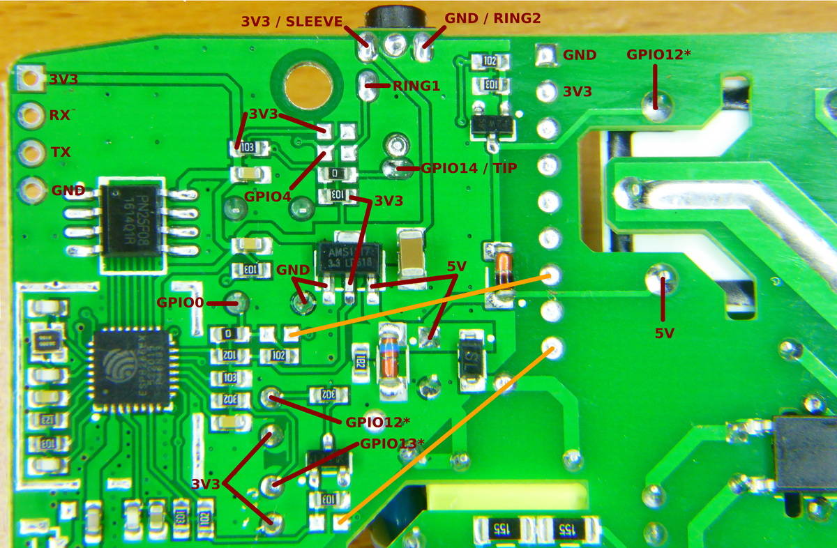
According to this diagram:
the tip of the jack plug for the external temp/humidity sensor is connected to GPIO14.
What’s the error in the text that you quoted from my smart socket post?
Pete.
o you said that the switch was gpio=0
so the sensor is 14…then why on earth can’t I get a reading. I also can’t get the switch to work with this piece of code (in the loop)
  int state;
  state = digitalRead(1);
digitalWrite(13, state); // affect the blue LED by the button stateBecause of this?
https://github.com/arendst/Sonoff-Tasmota/issues/735
What is important from this reading: The AM2301 should work but requires some library tweaking.
I don’t get it: If you know the button is wired to GPIO0 (and it is), then why on earth you are testing GPIO1?? ![]()
facepalm (and it works!)
final part is the sensor. It appears that arendst had already fixed it and I have that dht file…so I don’t get it why its not working.
Well, with this one I cannot help any further. Take a look at Tasmota’s sources? Read? compare… Fix the library… 
yup, you two have been great support. Im currently reading xsns_06_dht.ino and fingers crossed to see if I can get that working with my code. We’ll see… Basically I have every part working now for the sonoff. I just need that sensor input and then I can start with the actual code.
Yes, I said that I think the physical button on the Sonoff is connected to GPIO0. The code I linked you to was for a different type of smart switch, where the switch is linked to GPIO1, which is why I said that you’d need to change the GPIO settings to suit your Sonoff.
Pete.