I’m using the Wemos D1/ESP8266 WIFI / Blink Blink example.
Copy/paste the code, fill in the parameters for WIFI en Auth.
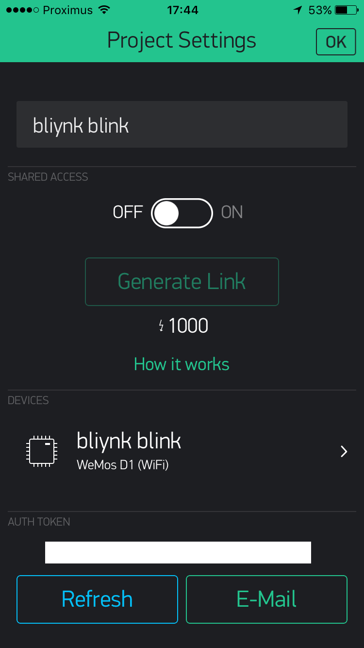
I’m getting this message then which indicates I’m setup, but nothing happens when I press the button on Blynk.(set to D3).
Is there a way to see what is coming from the Blynk-server, so that at least I can see that the signal is being received ?
Honestly, the project looks nice, but documentation and getting started wise, this is about the worst I’ve seen in years … each time I think found the right place for the info, only half of the info is available (either only the code, or only the Blynk info).
Any help would be greatly appreciated. (Apologies for the frustrated tone in the message).
Looking at the brief “How to control anything with Blynk app” notes I suspect the problem relates to a misunderstanding with the pins.
It refers to digital pin D3 and the WeMos, or any ESP for that, doesn’t have a digital pin 3.
You have a pin marked D3 on the WeMos but it’s not digital pin 3 it’s digital pin 0 (see https://wiki.wemos.cc/products:d1:d1_mini). WeMos and other manufacturers decided to provide their own labelling to the pins for some bizarre reason and it leads to lots of problems.
@Pavlo can you please modify the docs so noob Blynkers understand digital pins are GPIO references and not the screen printed references on the WeMos and NodeMCU’s etc.
Edit: technically ESP’s do have a digital pin 3 but it’s the RX pin (digital pin 1 is TX) and best left well alone.
That wouldn’t work because the problem isn’t related to pins it’s related to pin labelling.
Check the pin map link I provided. It’s for the Mini because WeMos have removed the map for the full WeMos D1 from their site but I believe it’s the same general mapping.
WeMos did change at least 1 pin map between the original D1 and rev 2.
So to recap, the notes refer to GPIO numbers not WeMos pin labels, use the map.
It will get more confusing when you actually start coding for the WeMos because then there is a GPIO to pin label mapping system that can be used. I NEVER use D references for ESP’s, always GPIO references and a map.
Actually I have probably confused everyone, me included.
Blynk actually maps the WeMos pin labels to the relevant digital pins (GPIO).
So if you select a WeMos board in the app and then allocate a button to label D3 it will control GPIO 0.
In my defence, serious Blynkers hardly ever use digital pins as the virtual pins are so much more powerful.
Also for WeMos’ I normally select the generic ESP8266 board in the app as there are some features not available when you select WeMos.
Using a WeMos with Blynk is normally child’s play. Can’t undersand what your problem is.
Presumably you selected WeMos D1 device in the app, right?
You could try switching to the ESP8266 device and there you will see gp0, gp1, gp2 etc rather than “D” pins.
For the onboard LED you would want gp2. I think the LED is active LOW so the Blynk button will work in reverse i.e. ON will turn LED off etc. That’s another reason to use virtual pins but don’t consider that until you have completed this elementary step.
as per my last post, you will need to have the button in the off position to turn on the onboard LED.
You can change the labels in the app so OFF becomes ON etc but later you will move to virtual pins.
I understand, but have been toggling the buttons on and off so I agree the positions would be wrong but in one of the two I should see the LED come on right ?
 !
!