since android app latest update, i am trying to set a timer widget to turn on and off at set times, i also have a button assigned to digital pin 2, now it says the pin is busy so cannot set timer because i have the button ad hoc on off on pin 2 as well, all previous buttons with timers are all still ok with dual pin 2 allocation in button and widget, it’s only happening on newly created stuff. Only since the recent app update, any ideas?
can someone try setting a button to a digital pin for a device and then try setting a timer widget for the same pin same device?
@jasperdog confirmed but I thought it was always like that i.e. a pin can only be assigned to one widget, not two.
That is why you have virtual pins rather than limited digital pins.
So, V0 button to control digital pin 2, V1 timer to to control the same digital pin 2 etc.
Thanks for reply, i did have 2 timers set up the way i explained, i only have one now as i swapped a sonoff for a device that i made, when up and running i tried to link the timer to it and it said pin busy, the other timer and button still exist and are working both on digital pin 12 using a SONOFF. In my DIY unit i am using an ESP-01 using pin 2, i must admit the other working linked unit is a sonoff using pin 12. So i setup a test sonoff to see if i could replicate successfully but it said pin 12 busy. My conclusion is it only happened since the latest app update. My sketch is only the basic blynk as like this:-
#define BLYNK_PRINT Serial    // Comment this out to disable prints and save space
#include <ESP8266WiFi.h>
#include <BlynkSimpleEsp8266.h>

// You should get Auth Token in the Blynk App.
// Go to the Project Settings (nut icon).
char auth[] = "******************************************";

// Your WiFi credentials.
// Set password to "" for open networks.
char ssid[] = "**********";
char pass[] = "**************";
char server[] = "***************";

void setup()
{
  Serial.begin(115200);
  Blynk.begin(auth, ssid, pass, server);
}

void loop()
{
  Blynk.run();
}
and the app button and timer assigned to digital pin 2
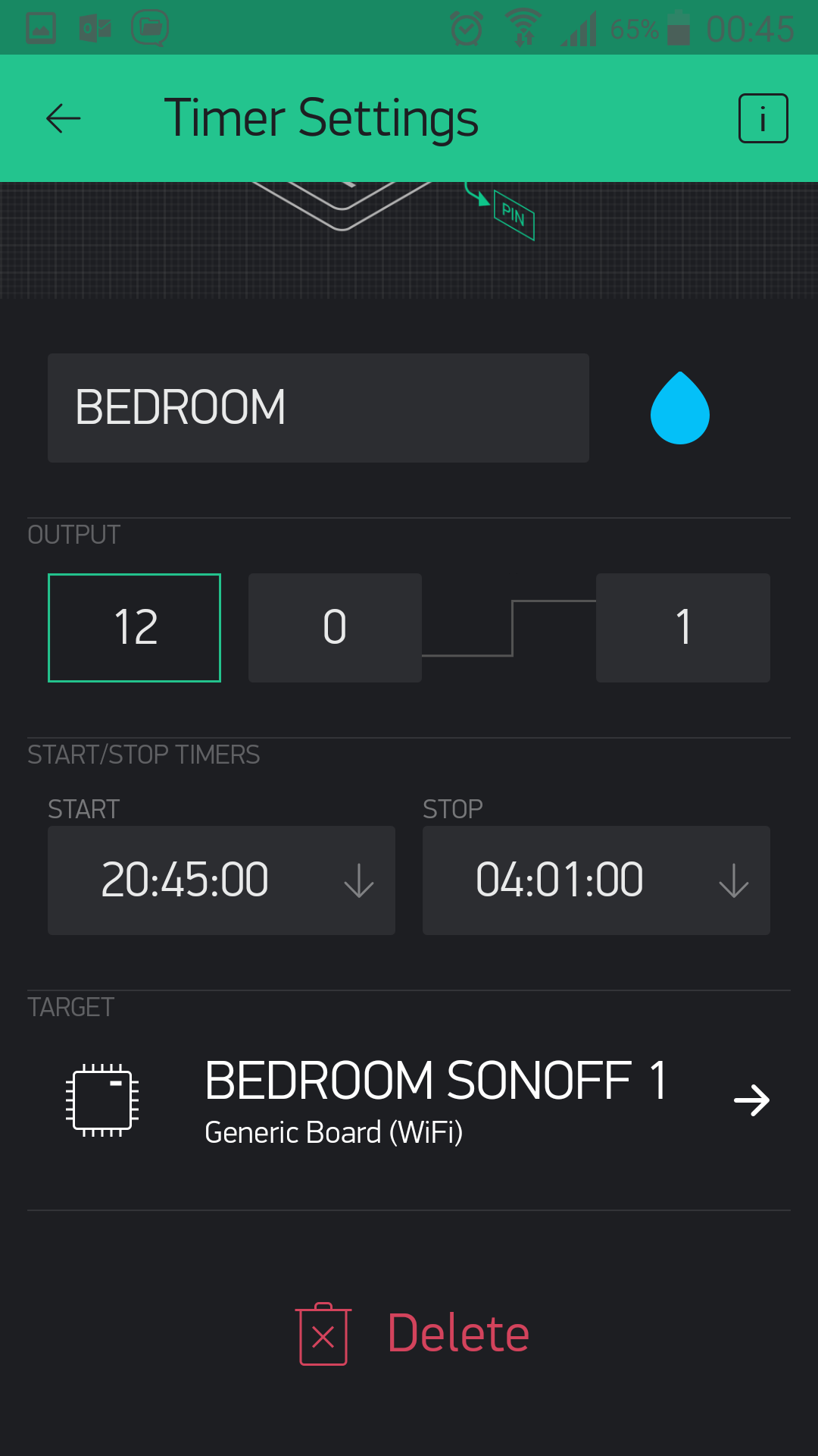
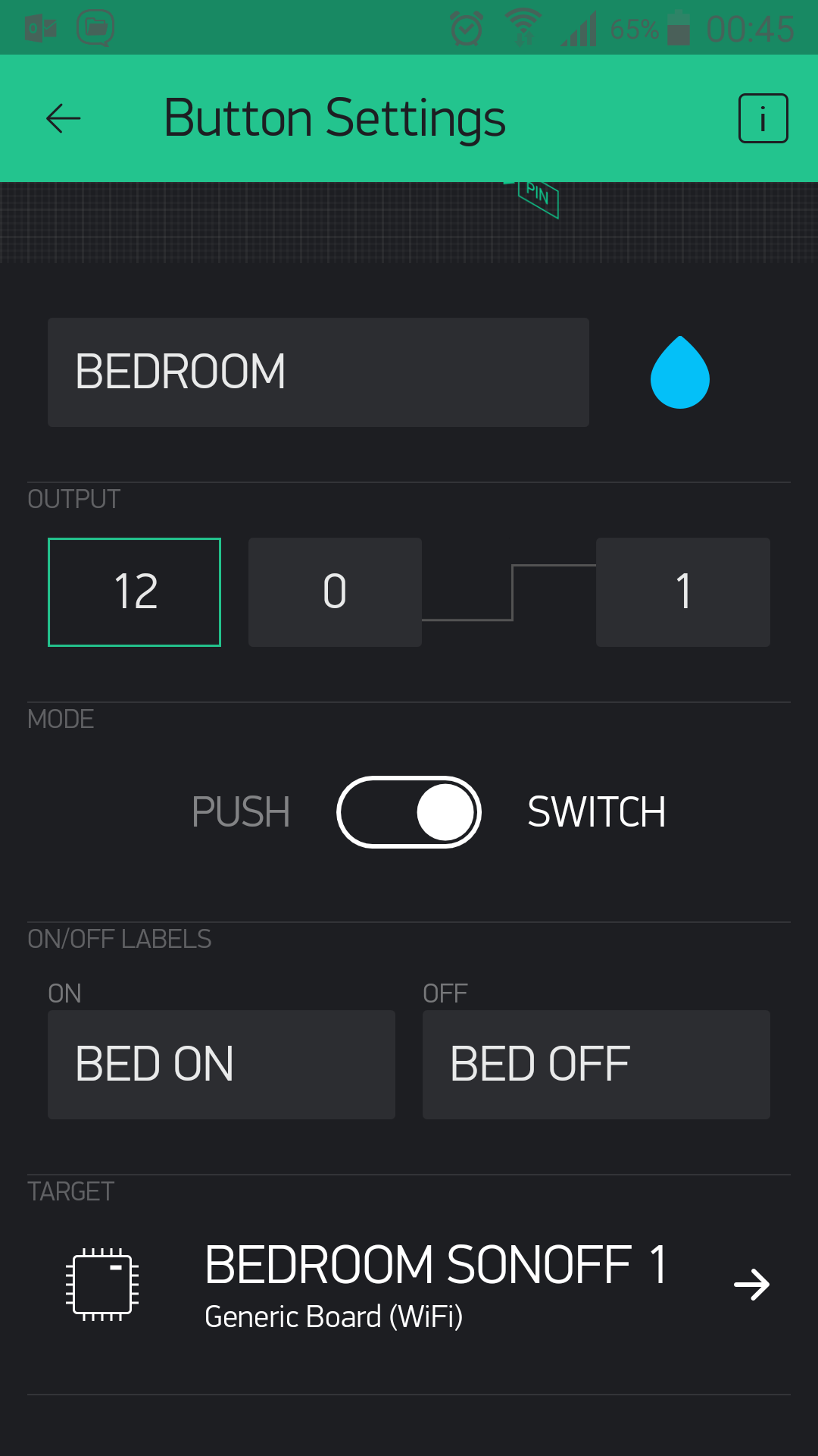
sorry @Costas I forgot to attach the screenshots of the existing link button timer for the same device,
Hi @Costas, can you explain using my sketch how i could use the virtual pins and that should then resolve any future problems, thanks in advance. I’m still not very good at coding.
@jasperdog take a look through the following sketch:
/* TimerWidget.ino https://community.blynk.cc/t/timer-widget/15658/6
   WeMos on board LED (active LOW) controlled by Timer AND Button widgets
*/
#define BLYNK_PRINT Serial
#include <ESP8266WiFi.h>
#include <BlynkSimpleEsp8266.h>

#define WEMOS_ON_BOARD_LED 2

char server[] = "blynk-cloud.com";
char ssid[]   = "xxx";
char pass[]   = "xxx";
char auth[]   = "xxx";


void setup()
{
  pinMode(WEMOS_ON_BOARD_LED, OUTPUT);
  digitalWrite(WEMOS_ON_BOARD_LED, HIGH); // LED OFF on bootup
  Serial.begin(115200);
  Blynk.begin(auth, ssid, pass, server);
  Blynk.virtualWrite(V1, 0); // button set to OFF on bootup
}


// WeMos on board LED is active LOW
BLYNK_WRITE(V0){      // Timer widget
  if (param.asInt() == 1) {
    Blynk.virtualWrite(V1, 1); // button set to ON from timer
    Serial.println("Timer ON activated");
  }
  else{
    Blynk.virtualWrite(V1, 0); // button set to OFF from timer
    Serial.println("Timer OFF activated");
  }
  Blynk.syncVirtual(V1);      // sync virtualWrite 0 / 1 to button widget
}

BLYNK_WRITE(V1){      // Button widget in SWITCH mode
  if (param.asInt() == 1) {
    digitalWrite(WEMOS_ON_BOARD_LED, LOW);
    Serial.println("LED ON");
  }
  else{
    digitalWrite(WEMOS_ON_BOARD_LED, HIGH);
    Serial.println("LED OFF");
  }
}

void loop()
{
  Blynk.run();
}
thanks @Costas for the reply, your sketch either activates or deactivates the timer, how do i still maintain ad hoc control of the same button device? do i write as V2?
V1 button still works independently of the Timer.
sorry, what i mean is to also have a Button to ad hoc turn device on off with a timer widget to repeat each day time on and time off.
The Timer on V0 will turn ON and OFF each day at the time you set.
oh i see so the button will be V1
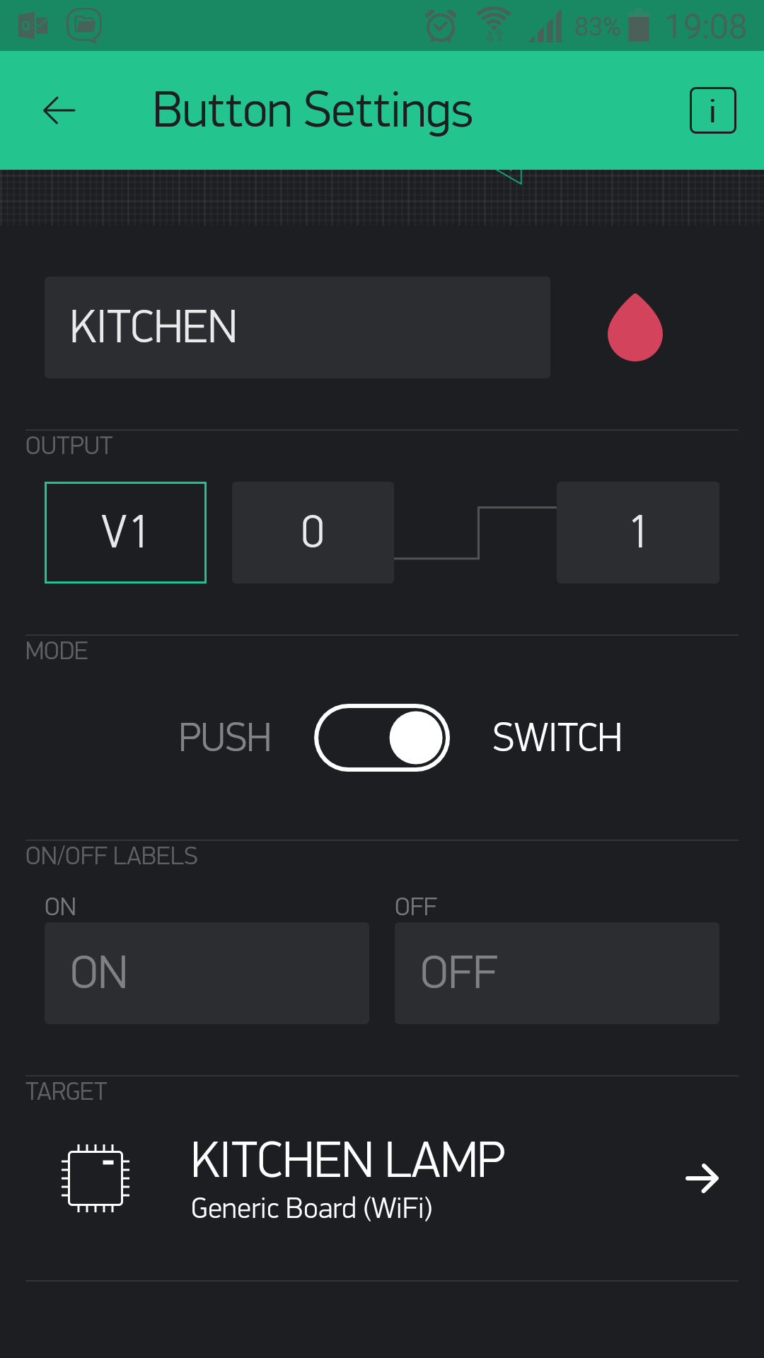
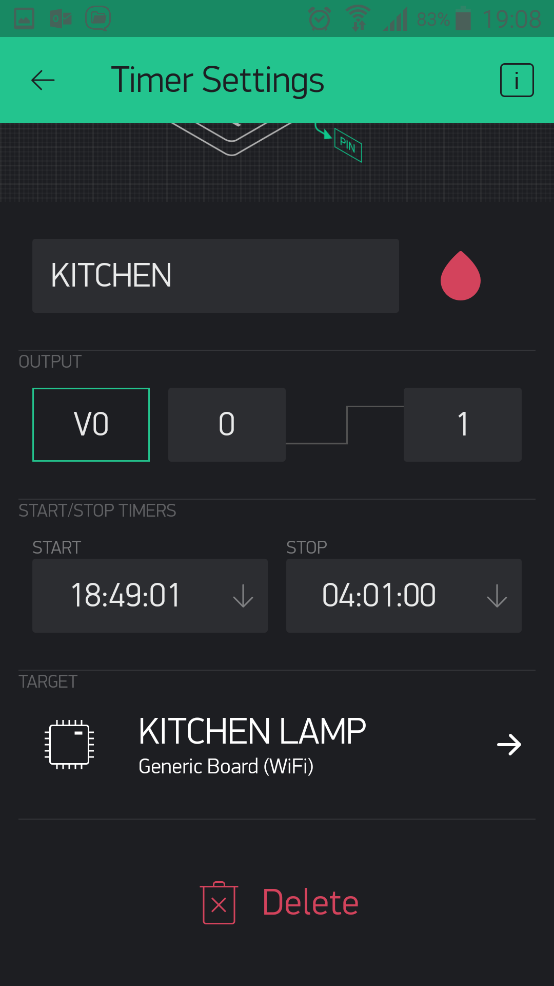
success !!! well done again @Costas many thanks.
just for info if using a standard ESP-01 module like i have, i amended the following:-
#define WEMOS_ON_BOARD_LED 2
TO
#define GPIO (2)
and reversed the HIGH LOW statements
tested both BUTTON and TIMER functions, both working.
also needed to amend baud rate to 115200 or it wouldn’t flash the chip.
screenshots of app stuff:-
Hi, I have the same problem, I have two timer and two button:
TIMER1 control Button1
TIMER2 control Button2
I see your code, so the right way is include Blynk.syncVirtual(button) to refresh the state of the button?
Let me know
Thank you
Hi, i think you can use the following or use 2 statements to correspond with your 2 Vpins;-
Blynk.syncAll()
or
Blynk.syncVirtual(V1);
Blynk.syncVirtual(V2);
if you insert your code it will help with your answer?
Thank you for replay.
I’ll copy my code and I have two question:
1)In BLYNK_CONNECTED() method I Sync single value in first connection (you can see in the code). After this, should I insert, for single value, methods BLYNK_WRITE(single value) to download from blynk server last value? My values are float and if I’ll try this:
BLYNK_WRITE(single value){
  float f = paramAsFloat();
}
doesn’t work!
2)As I told you, I have two timer and two button
TIMER1 control Button1
TIMER2 control Button2
This is right way to control button by timer?
BLYNK_WRITE(V9){  //control Timer Faretto

  if(param.asInt()==1){
    Blynk.virtualWrite(buttonFaretto10W, 1);  // START RELAY FARETTO
    //digitalWrite(relayFaretto10WD4, HIGH);
  }else{
    Blynk.virtualWrite(buttonFaretto10W, 0);   // STOP RELAY FARETTO
    //digitalWrite(relayFaretto10WD4, LOW);
    current_day = 0;
  }
  Blynk.syncVirtual(buttonFaretto10W);
}
this is my code:
#include <Blynk.h>

#include <Wire.h>
#include <Adafruit_INA219.h>
#define BLYNK_PRINT Serial


#include <ESP8266WiFi.h>
#include <BlynkSimpleEsp8266.h>

char auth[] = "++++++";  //  TOKEN DI PROVA
//char auth[] = "+++++++";

Adafruit_INA219 ina219;

char ssid[] = "";
char pass[] = "";

//char ssid[] = "";
//char pass[] = "";

float shuntvoltage = 0;
float busvoltage = 0;
float current_mA = 0;
float current_h = 0;
float current_day = 0;
float loadvoltage = 0;
float power_mW = 0;
float energy = 0;

boolean isFirstConnect = true;
boolean isConnesso;

unsigned long previousMillis = 0;
unsigned long interval = 100;
unsigned long currentMillis = 0;

#define relayFaretto10WD4 D4
#define relayMadonnaD5 D5
#define greenLEDD7 D7
#define redLEDD8 D8

#define buttonFaretto10W V0  // >> D4
#define buttonMadonna V1     // >> D5
#define correnteIstantanea V4
#define potenzaIstantanea V5
#define energiaTotale V6
#define correnteTotale V7
#define correnteTotaleDay V8


BlynkTimer timer;

void setup(void) {

  Blynk.begin(auth, ssid, pass);
  pinMode(greenLEDD7, OUTPUT);
  pinMode(redLEDD8, OUTPUT);
  timer.setInterval(1000L, sendIna219Values);
  ina219.begin();

}


void loop(void){

  letturaPannello();
  Blynk.run();
  timer.run();

}


void letturaPannello(){

  isConnesso = controllaConnessione();

  if(isConnesso){

    currentMillis = millis();

    if (currentMillis - previousMillis >= interval){
       previousMillis = currentMillis;
       ina219values();  //  READ SENSOR
    }
  }else{
    Blynk.connect();
  }

}


boolean controllaConnessione(){

  if(Blynk.connected()){

    digitalWrite(greenLEDD7, HIGH);
    digitalWrite(redLEDD8, LOW);
    return true;

  }else{

    digitalWrite(greenLEDD7, LOW);
    digitalWrite(redLEDD8, HIGH);
    return false;

  }

}


void ina219values() {

  shuntvoltage = ina219.getShuntVoltage_mV();
  busvoltage = ina219.getBusVoltage_V();
  current_mA = abs(ina219.getCurrent_mA());
  power_mW = ina219.getPower_mW();
  loadvoltage = busvoltage + (shuntvoltage / 1000);
  energy = energy + loadvoltage * current_mA / 3600;  // conteggio energia totale
  current_h = current_h + current_mA / 3600;   // conteggio corrente totale
  current_day = current_day + current_mA / 3600;   // conteggio corrente giornaliero

}


void sendIna219Values(){
  Blynk.virtualWrite(correnteIstantanea, current_mA / 1000);  // VIRTUAL PIN   V4
  Blynk.virtualWrite(potenzaIstantanea, power_mW / 1000);  // VIRTUAL PIN   V5
  Blynk.virtualWrite(energiaTotale, energy / 1000);  // VIRTUAL PIN  V6
  Blynk.virtualWrite(correnteTotale, current_h / 1000);  // VIRTUAL PIN   V7
  Blynk.virtualWrite(correnteTotaleDay, current_day / 1000);  // VIRTUAL PIN  V8
}

BLYNK_CONNECTED() {
  if (isFirstConnect) {
    Blynk.syncVirtual(buttonFaretto10W);
    Blynk.syncVirtual(buttonMadonna);
    Blynk.syncVirtual(correnteIstantanea);
    Blynk.syncVirtual(potenzaIstantanea);
    Blynk.syncVirtual(energiaTotale);
    Blynk.syncVirtual(correnteTotale);
    Blynk.syncVirtual(correnteTotaleDay);
    Blynk.syncVirtual(V9);
    Blynk.syncVirtual(V10);
    Blynk.syncVirtual(V11);
    Blynk.syncVirtual(V12);   //V9  V10 V11 V12  sono TIMER
    isFirstConnect = false;
  }
}


BLYNK_WRITE(buttonFaretto10W){  //controllo VIRTUAL Button Faretto

  if(param.asInt()==1){
    digitalWrite(relayFaretto10WD4, HIGH);  // START RELAY FARETTO
  }else{
    digitalWrite(relayFaretto10WD4, LOW);   // STOP RELAY FARETTO
  }
}


BLYNK_WRITE(buttonMadonna){  //controllo VIRTUAL Button Madonna

  if(param.asInt()==1){
    digitalWrite(relayMadonnaD5, HIGH);  // START RELAY MADONNA
  }else{
    digitalWrite(relayMadonnaD5, LOW);   // STOP RELAY MADONNA
  }
}


BLYNK_WRITE(V9){  //control Timer Faretto

  if(param.asInt()==1){
    Blynk.virtualWrite(buttonFaretto10W, 1);  // START RELAY FARETTO
    //digitalWrite(relayFaretto10WD4, HIGH);
  }else{
    Blynk.virtualWrite(buttonFaretto10W, 0);   // STOP RELAY FARETTO
    //digitalWrite(relayFaretto10WD4, LOW);
    current_day = 0;
  }
  Blynk.syncVirtual(buttonFaretto10W);
}

BLYNK_WRITE(V10){  //control Timer Madonna

  if(param.asInt()==1){
    Blynk.virtualWrite(buttonMadonna, 1);   // START RELAY MADONNA
    //digitalWrite(relayMadonnaD5, HIGH);
  }else{
    Blynk.virtualWrite(buttonMadonna, 0);  // STOP RELAY MADONNA
    //digitalWrite(relayMadonnaD5, LOW);
    current_day = 0;
  }
  Blynk.syncVirtual(buttonMadonna);
}


void stampaValori(){
    Serial.print("Bus Voltage:   "); Serial.print(busvoltage); Serial.println(" V");
    Serial.print("Shunt Voltage: "); Serial.print(shuntvoltage); Serial.println(" mV");
    Serial.print("Load Voltage:  "); Serial.print(loadvoltage); Serial.println(" V");
    Serial.print("Current:       "); Serial.print(current_mA); Serial.println(" mA");
    Serial.print("Power:         "); Serial.print(power_mW); Serial.println(" mW");
    Serial.print("Energia:         "); Serial.print(energy); Serial.println(" mWh");
    Serial.print("CorrenteH:         "); Serial.print(current_h); Serial.println(" mAh");
    Serial.print("CorrenteHDay:         "); Serial.print(current_day); Serial.println(" mAh");
    Serial.println("");
}For point 1) I restore data in this mode:
BLYNK_WRITE(correnteIstantanea){
  current_mA = param[0].asFloat();
}

BLYNK_WRITE(potenzaIstantanea){
  power_mW = param[0].asFloat();
}

BLYNK_WRITE(energiaTotale){
  energy = param[0].asFloat();
}

BLYNK_WRITE(correnteTotale){
  current_h = param[0].asFloat();
}

BLYNK_WRITE(correnteTotaleDay){
  current_day = param[0].asFloat();
}
In this mode I haven’t problem and I correctly!
I had insert param[0], without [0] doesn’t compile! Why?
Thank you
Hi everyone, I don’t see reply, my only question is this:
Having a relay controlled by Button and timer that control Button, the best combination is?
Timer V0 >>> Button V1 >>> Relay D1 ??
Or can I use one virtual pin for timer and button as:
Timer V0 >>> Button V0 >>> Relay D1 ??
With one virtual pin not always works, infact one virtual pin is busy. So can you give me confirmation that the best combination is using two virtual pin?
Thank you
No, that’s not the way to do it. Use different virtual pins.
Pete.