I have a wemos D1 mini clone and I’m trying to use a soil moisture sensor like this: Soil Moisture sensor on Ebay
If I connect the sensor to the VCC (3.3V) and the GND to the same ground the wemos clone is getting everything works ok.
If I try to connect the VCC of the sensor to the digital pin (D2 for my example) it doesn’t work and show 0 or a number close to it…
everything else is working fine… just this part…
I checked that the sensor really gets power and it does and outputs the correct voltage on the signal pin so that is working as well.
am I doing something wrong?
int soilSensorValue = analogRead(A0);
Blynk.virtualWrite(V11,map(soilSensorValue,0,1024,0,100));
also tried that:
//Soil Sensor Reading:
int SoilSensorReading()
{
    digitalWrite(D2, HIGH);
    int CurrentRead = analogRead(A0);
    digitalWrite(D2, LOW);
}
if I do it on the first example I get the results more or less… but I can live with them…
On the second example I get nothing… always 0 or close to that.
Please help me… I’ve been trying to find the solution for the last 4 hours and got nothing.
I read somewhere that if you keep it connected all time you reduce the sensor life span… so you hook it up to a digital pin and when you want to read the moisture you put it to HIGH and read from the analog pin… and then put the digital (VCC) pin to LOW…
if you say that it is nonsense then I’ll just use it without.
@sagirokach that is correct. What does Serial Monitor show if you change it to:
//Soil Sensor Reading:
int SoilSensorReading()
{
    digitalWrite(D2, HIGH);
    delay(20);
    int CurrentRead = analogRead(A0);
    Serial.println(CurrentRead);
    digitalWrite(D2, LOW);
}
Technically the WeMos can only accept 3.2V on the analogue port, not 3.3V. Most of the time it’s not a problem but if you have a pot trim it down to 3.2V.
Not a bad idea on principle, however you need to take into consideration the source current limit of ESP pins… reportedly 12ma max (less if you are also drawing current from other pins as well).
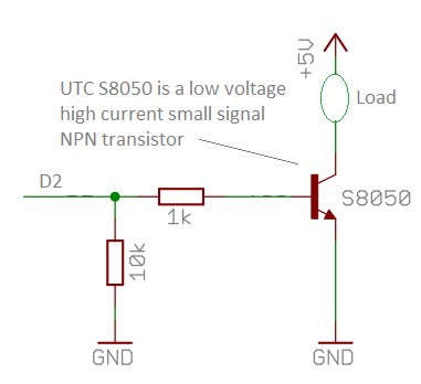
If you really want to go that route, then use a transistor or optoisolator inline with the pin, to switch an external, higher current source, of 3.3v for the sensors needs.
If the sensor is drawing current beyond source capacity, the source voltage will also drop.
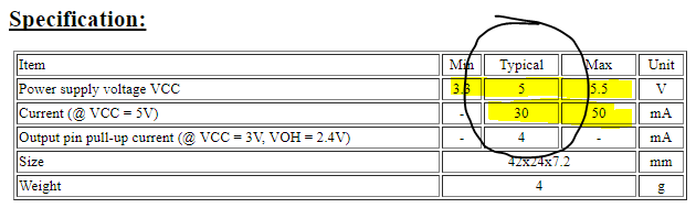
That sensor expects between 3.3v and 5.5v @ between 30-50mA, so you need to hook it up directly to a 5v power source for now (EDIT use 3.3v when sensor is hooked up to ESP)… until you can understand the transistor switch solution.
@Costas Ah, yes… good point… I am still thinking in Arduino mode
@sagirokach - As stated above, uses a good 3.3v source then… the 3.3v pin on the ESP may not supply enough current on it’s own. If using an external 3.3v source, make sure it’s ground is shared with the ESP ground.