@sagirokach like @Gunner has it but with a 3.3V load 
You should be powering the sensor with 5v (same power source as the D1), then voltage divide the signal output pin to 1v which then goes in to A0.
I only say this because im sure im the only one here who has actually played with one of those sensors in a project 
1 Like
@Jamin the WeMos is designed for 3.2V on A0 not 1V. You could use the 5V but you only need to drop the return voltage down to 3.2V.
Hmmm whenever I have ever put in more than 1v on the ADC on the D1 mini, it blows up!
But those could have been d1 clones without the 3.2/1v divider built in.
Found this on another site… so thats handy.
The A0 input of the Wemos D1 mini is connected to the ADC input of the ESP-12 through a 3.2/1 voltage divider, consisting of a 220k and 100k resistor.
Good thing I only buy genuine WeMos products now
I think all the clones are set to 3.2V too, you are perhaps thinking of bare ESP’s.
I discussed the voltage dividers with “Mr WeMos” and asked why he picked such dreadful resistors i.e. the A0 will not technically accept the operating voltage of the WeMos itself. Answer, “we copied the nodemcu”.
In fairness after we hassled him he did change some of the labels on his website but some pages still have a mix of 3.2V and 3.3V maximum.
1 Like
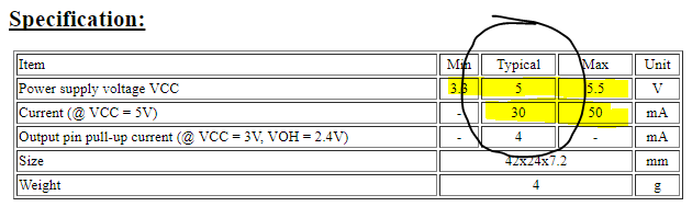
The 5V pin on a WeMos is capable of handling 500mA to 1000mA depending which WeMos you have (Pro has 1000mA). Presumably 3.3V can handle way more than 50mA too. It’s just the data pins that have very low current ratings.
Exactly my point (about the 2nd part)… don’t put that load (the sensors power) on a GPIO pin in order to turn it ON and OFF…
@Gunner actually with Arduino’s using data pins for V and Gnd was something I did on a regular basis and never noticed any ill effects. Perhaps the components we were hooking up had a relatively low current draw but I would say considerably more than the stated max for the pin.
@Costas Yes… The Arduino’s MAX is 40mA on a pin, but the ESP8266 is only 12-18mA (depending on source)… so while switching/powering a sensor on an Arduino might be survivable, I don’t think the ESP will make it.
Hey @Gunner,
I did ponder about this.  and I tried to implement it with my project.
I didn’t connect the 10K resistor, is it necessary? cause it didn’t work when I did.
I’m using 2n3904 transistor… cause it’s the only one I have right now. is it good enough for the job? (it works so I assume it is)
Do I need the 5V on the load? or can I use the 3.3V?
This is my code:
int GetSoilReading()
{
  digitalWrite(SOILSENSORPOWER,HIGH);
  delay(50);
  int Reading1 = analogRead(A0);
  terminal.println(Reading1);
  int Reading2 = analogRead(A0);
  terminal.println(Reading2);
  terminal.flush();
  delay(100);
  digitalWrite(SOILSENSORPOWER,LOW);
  return (Reading1 + Reading2) / 2;
}
and when I run this I get values closer to the 100%… I just want to make sure I did it right…
if you have any more things to give me to ponder about I’ll take them gladly.
I did ponder about this for 3 days now. 
Thanks again.
Two months of pondering seems to have helped you… but left me scratching my head going… “What were we talking about anyhow?” ![]()
A complete reread of this topic later…
OK, that randomly-grabbed-from-Google-circuit was a way of switching a larger load (5v with larger current - dependent on the transistor, yours is aprox 40v @ 200mA MAX, just fine for your sensor) ) from a similar or smaller TTL level pin (in the case of an ESP, 3.3v @ 12-18mA MAX).
The 10K resistor is for use as a pulldown (keeps that pin LOW until otherwise forced HIGH)… I don’t understand why its presence between the pin and GND should have caused any issues… but if it works without it (as in NO GND connection there at all, otherwise it becomes a dead short when pin pulled HIGH), then well… fine I guess ![]()
I believe that sensor really requires the 5v for it’s power… but that is fine, this was what the above circuit was for ![]()
ok so I want to understand that I understand.
Right now with the transistor in the circuit I have roughly 2.6 voltage drop when I check with the multimeter between the collector and emitter of the transistor as I understand it’s not 3.3V because the transistor takes 0.6 upon itself. Now if a current comes from the esp from on the digital pins I get 3.3V on the base. isn’t that wrong? should I have less coming from the pin and if so how can I do it right? add another resistor? ground the digital pin like you posted before?
Please help me understand what am I doing wrong… because right now my readings are 102% of humidity when I didn’t water the plant for 2 days… and before I introduced the transistor to the system it was around 85… 
Thanks again in advance.
Well, first… the transistor circuit (should) only turn ON and OFF the power to your sensor, so as long as the transistor base reaches saturation levels (0.85-0.95v if I am reading the data sheet correctly), then the voltage/current passing through the Collector and Emitter (which should be the 5v source for powering your sensor), then the load (your sensor) should be fully powered.
As for what it senses, which pin you use to read that signal, and how you calibrate it… well that is up to the rest of your setup.
If you need to test that, without the added uncertainty of the power switch circuit, simple bypass it and run your sensor power directly, and full time, off the 5v source.
so first of all I run the sensor through 3.3V of the esp not the 5V.
second of all I measure it with the A0 pin of the esp.
and it does turn on and off when the base which is a digital pin (D5) goes high and low which happens every half an hour.
but I think that something is wrong with it… because the base gets 3.3V from the digital pin, and the emitter - collector has 2.6V… as I understood thee base should only “connect” the emitter - collector bridge with low current and low voltage… did I understand it right?
when I run the sensor directly all the time it shows the humidity around 85%… and now with the transistor it’s around 97-102%…
Well, that is probably part of your problem right there… too low of voltage and probably low current as well to power it properly… the 3.3v pin on an ESP is not capable of driving much. And using it makes the whole transistor circuit almost meaningless as it is MEANT to control a higher voltage sensor without risking your ESP.
BTW, none of this is really Blynk specific… this is more “practical electronics 101” ![]()
ok I’ll see what I can do…
Thank you so much for helping me figure everything out.
Sorry @Gunner to open this subject again but I want to run this by you to know that I’m doing it right.
Since I connected everything and I checked that it works… (no power when the sensor doesn’t need to be powered and so on) The values I get are a bit jumpy… I get 990 out of 1024 and then 1003, it sometimes drops 20 values and raise by 10 and just jump around…
Is there anything I can do to “smooth” the curve? because before the transistor it was perfect… went down slowly and when I watered it went up again and started going down again…
Do you have any idea as to why this is happening? or any solution?
I changed the code to sample the humidity 10 times and give me an average… but that is all I could think of…
Thanks again in advance!
Well, just a guess without seeing current code, but perhaps you are toggling the “power” control too much… I would code so your sensor turns on, has a “warm up” time of perhaps 0.5 - 1 second?? do all your readings and averaging, and only then shut off the power to the sensor.
There is also the possibility that your transistor circuit may not be saturating, i.e. switching the full 5v?? That would probably require a multimeter to confirm that.
BTW, a simple relay would also do the same job… just a bit bulkier.
Yeah I want to do it as small as possible…
This is the current code:
int GetSoilReading()
{
  digitalWrite(SOILSENSORPOWER,HIGH);
  delay(50);
  int Reading = 0;
  for(int i = 0; i < 10; i++)
  {
    Reading += analogRead(A0);
  }
  delay(100);
  digitalWrite(SOILSENSORPOWER,LOW);
  return Reading / 10;
}
should I put a bigger delay? 500?
Changed the delay to 500 and then 250 and still the reading jumps all over the place. from 920 898 and then 910…
I don’t know what to do… 