Simultaneous conection between Arduino Mega and ESP 12e(module but created a breakout board circuit ready to connect to arduino)

I created a breakout board for ESP-12e based in this instructables

)

and was able to use the AT codes to communicate via Arduino IDE serial monitor

the following day i uploaded a sketch that connects to my network, via generic esp8266 board, it was successfully connecting to my wifi.

then i upload a simple led blink sketch to Arduino Mega Board it was success, but when i open serial monitor it says
“ESP is not responding”

later i uploaded sketch that detects wifi shield with software serial (10,11)
it saying in the serial monitor no wifi shield is detected.

Question
What do i need to upload to ESP12 module in order for it to communicate to Arduino Mega?

Any suggestion, I refered to this link but i dont think this could help, [SOLVED] Esp8266 as WiFi shield setup

Thank you

Congratulation, you have now converted your ESP to standalone mode…

http://help.blynk.cc/how-to-connect-different-hardware-with-blynk/arduino/esp8266-standalone

Reflash AT firmware… check with supplier or Google for AT firmware installation options/methods.

http://help.blynk.cc/how-to-connect-different-hardware-with-blynk/arduino/esp8266-with-at-firmware

I tried flashing it with this tutorial

it was successful, then i opened Arduino IDE for serial monitoring
when switched to normal mode this showed up

ets Jan  8 2013,rst cause:2, boot mode:(3,6)

load 0x40100000, len 23200, room 16 
tail 0
chksum 0xef
load 0x88888888, len -2004318072, room 8 
flash read err, ets_unpack_flash_code
ets_main.c 

what could be the possible fix, i tried to google it but i could find definite answers?

Please expand on precisely what you mean by this.

GPIO0 is pulled up by 10k
RST pulled up by 10k
GPIO pulled down by 10k

upon powering the esp 12

pn configuration when the error come out
txd - tx(pin1)
rxd - rx(pin0)

i also tested
txd -rz
rxd -tx
nothing happend

Not sure you need a fix.

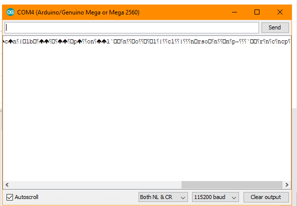
What you are seeing is the standard serial data from an ESP.

Now that you have it back in AT mode make sure you don’t flash any Arduino sketches to the ESP.

Flash your Arduino sketch to the Mega and if you have all the right connections for ESP “you are good to go” (that’s a highly technical term used by IT guru’s).

is after flashing, could i still issue AT commands?Capture5,
i have tact switch for the hardware reset and this showed in serial monitor

and even issued simple “AT” command and nothing happened, Is this normal?

When I say flashing I mean with the Arduino IDE, don’t do it if you want to use the crappy Arduino with ESP connection method. Really you should be looking at the ESP with Mega shield method.

Fairly normal and part of the reason it’s a crappy way to use Blynk.

Look up the AT command for setting the baud rate of the ESP to the snails pace required by the Mega of 9600 and ensure your sketches for the Mega also use 9600.

You will then probably have a handful of other problems but let us know about these when you get to them.

/* Comment this out to disable prints and save space */
#define BLYNK_PRINT Serial

#include <ESP8266_Lib.h>
#include <BlynkSimpleShieldEsp8266.h>

char auth = “7c71093b6c204e5badc24bb98bb46f7e”;

char ssid = “PLDTHOMEDSL*****”;
char pass = “*************”;

// Hardware Serial on Mega, Leonardo, Micro…
#define EspSerial Serial1

// or Software Serial on Uno, Nano…
//#include <SoftwareSerial.h>
//SoftwareSerial EspSerial(10, 11); // RX, TX

// Your ESP8266 baud rate:
#define ESP8266_BAUD 115200

ESP8266 wifi(&EspSerial);

void setup()
{
// Debug console
Serial.begin(9600);

delay(100);

// Set ESP8266 baud rate
EspSerial.begin(ESP8266_BAUD);
delay(100);

Blynk.begin(auth, wifi, ssid, pass);
}

void loop()
{
Blynk.run();
}

i uploaded this sketch to arduino mega
pin configuration
txd - pin 10
rxd - pin 11

it could not connect it saysCapture6

i also tried external 5v to power my ams1117 regulator to esp12

esp configuration
i have voltage divider resistor at rx pin of esp12
EN is connected to vcc with a 10k resistor
GPIO0 is pulled up by 10k resistor
GPIO15 pulled down by 10k resistor
RST pin has pullup resistor 10k

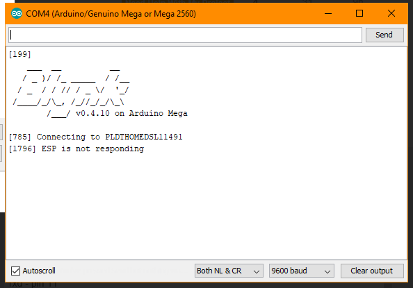
@princenpg22 “ESP is not responding” is the message that I would say most shield users see when they start out. Formerly they saw a rather cryptic message of “Cannot disable echo”.

Cannot disable echo is one of most “popular” phrases on this site.

Search for both phrases and work through the 87 possible fixes, or simply switch your hardware around to mighty ESP with slow Mega shield :slight_smile:

I will look it in other post related this problem

Thank you

We have decided to purchase a NodeMCU to ease head ache in looking to solve the error.

Another question, If just in case is it possible to use the esp 12e module only (with required voltage reg and division) to have a standalone code, and communicate to arduino via software serial?

Yes… just like any other ESP, within GPIO and memory limitations.

Yes as well… but If you set up programming via OTA then you could probably use the Hardware TX/RX pins, or possibly i2c and a communications library like this…

Ohh, thats a great motivation to continue to know more, since i tried reflashing several binaries, but using standalone code in my esp12e module still connects to the internet

Thanks

That is a “feature” of the ESP… they retain last WiFi credentials. If you need to you can wipe them out by overwriting the flash memory. You will need to Google that as it is not something I recall off the top-o-me head.