I came across a cheap ($6) ESP8266 board that includes an AC power supply, esp8266 chip, 2x relays and footprint for a DHT11/DHT22 sensors.
It’s super easy to get started with Blynk using this board, so I figured I could post a little tutorial for those interested.
Hardware needed
1x relay board
1x DHT22 temperature and humidity sensor. You could also use the DHT11, which is a little cheaper but less accurate.
1x usb to serial adapter.
I got the first 2 from electrodragon.com, already had the usb to serial adapter.
http://www.electrodragon.com/product/wifi-iot-relay-board-based-esp8266/
http://www.electrodragon.com/product/dht22-pre-order-link/
http://www.electrodragon.com/product/cp2102-usb-ttl-uart-module-v2/
There’s a jumper on the back of the usb to serial adapter that needs to be soldered to make it 3.3v. Make sure to do that as 5v may damage your relay board. The DHT22 sensor also has 4 pins that need to be soldered to the relay board.
Software you need
Arduino - https://www.arduino.cc/en/Main/Software
ESP8266 arduino - https://github.com/esp8266/Arduino
DHT library for arduino - https://github.com/adafruit/DHT-sensor-library
Blynk for android - http://www.blynk.cc/getting-started/
Install all of these libraries, following instructions on the websites.
Connect the esp8266 to the usb to serial adapter
RX on USB to TX on relay board
TX on USB to RX on relay board
VCC on USB to 3.3v on relay board
GND ong USB to GND on relay board
Code
#define BLYNK_PRINT Serial    // Comment this out to disable prints and save space
#include <ESP8266WiFi.h>
#include <BlynkSimpleEsp8266.h>
#include <ESP8266HTTPClient.h>
#include <Phant.h>


#include <DHT.h>
#define DHTTYPE DHT22
#define DHTPIN  14
DHT dht(DHTPIN, DHTTYPE, 11);
float humidity, temp;  // Values read from sensor
unsigned long previousMillis = 0;
const long interval = 15000;          // interval at which to read sensor / Update values

// You should get Auth Token in the Blynk App.
// Go to the Project Settings (nut icon).
char auth[] = "your blink api key";

void setup()
{
  Serial.begin(115200);
  Blynk.begin(auth, "APname", "AP passkey");
  dht.begin();
}

void gettemperature() {
  unsigned long currentMillis = millis();

  if(currentMillis - previousMillis >= interval) {
    // save the last time you read the sensor
    previousMillis = currentMillis;

    // Reading temperature for humidity takes about 250 milliseconds!
    // Sensor readings may also be up to 2 seconds 'old' (it's a very slow sensor)
    humidity = dht.readHumidity();          // Read humidity (percent)
    temp = dht.readTemperature(false);     // Read temperature as Fahrenheit
    Blynk.virtualWrite(V0, temp);
    Blynk.virtualWrite(V1, humidity);

    // Check if any reads failed and exit early (to try again).
    if (isnan(humidity) || isnan(temp)) {
      Serial.println("Failed to read from DHT sensor!");
      return;
    }
  }
}

bool isFirstConnect = true;
BLYNK_CONNECTED(){
  if (isFirstConnect)
  {
    Blynk.syncAll();
    isFirstConnect = false;
  }
}

void loop()
{
  Blynk.run();
  gettemperature();
}
Change the Blynk API key to the API key you get in the Blynk app, and change the APname and passkey to your wifi login credentials.
Finally select the correct COM port in arduino, and select boards etc as shown here:
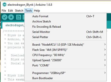
To program the relay board you need to hold the BTN2 on the relay board while you turn it on. Keep it held down for a few moments while the board starts up. You may hear some clicking of the relays. Press upload in arduino and the code will be uploaded to the relay board. If it fails, try disconnecting the power from it and repeat the upload steps. It sometimes takes a couple of tries to get the board in flash mode.
Blynk setup
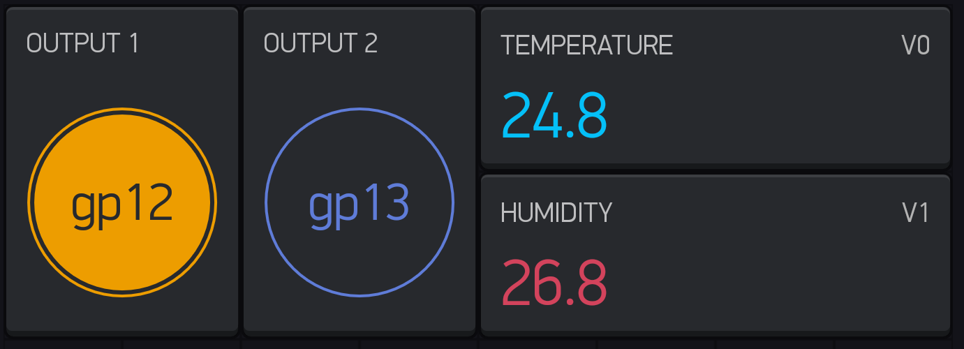
There’s just a couple of things you need to know to be able to set yout Blynk dashboard up properly. First, V0 is for temperature, V1 is for humidity. Secondly, gp13 and gp14 are for the relay outputs. You can add buttons for the relay outputs, Value Display or Labeled Value for the environmental values. And finally, if you like graphs and historic data you can add a history graph for temperature and humidity.
This is what my setup looks like (I have 2 relay boards running right now, at work and at home)
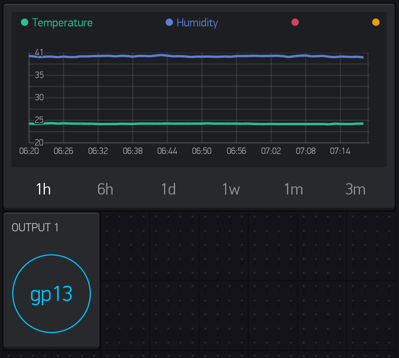
I would have more widgets, but I ran out of energy and can’t buy more right now.
Hopefully this guide will help some of you guys take your first Blynk steps.
