I have a temperature monitor with two sensors, it sends notifications if temperature is below a setpoint AND the equipement is running ( no need to maintain temp all the time only when operating)
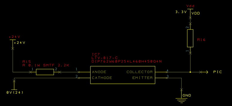
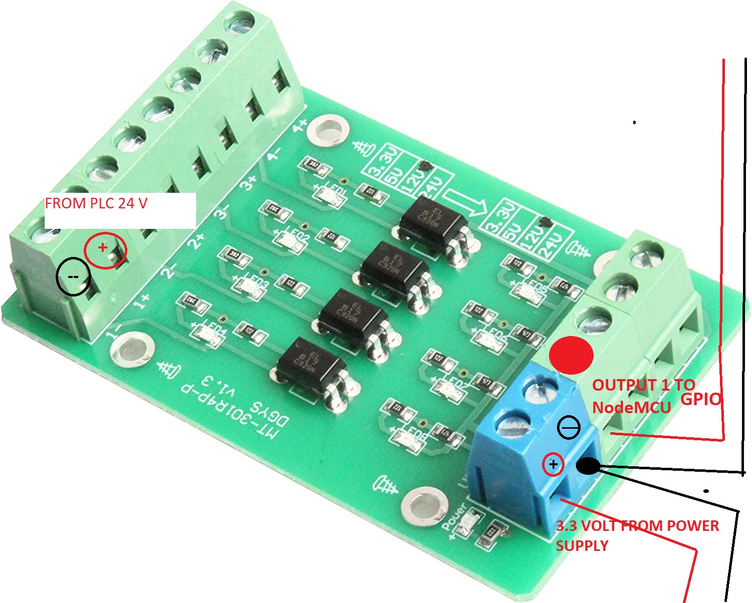
The project worked fine at first using a relay to tell state, 24V from plc would close relay and that would make pin0 high, now after I added a display (I2C ) they thing went haywire when getting the signal, I figured that it was too much power being pulled since the signal wire was far from Nodemcu ESP8266 so I added an optocoupler, powered externally and bonded the grounds so the 3.3 volt signal from opto would make pin0 high… well it does not work. everything works fine until the machine runs, then the readings are very erratic.
the module is a nodemcu ESP8266
#define BLYNK_TEMPLATE_ID "TMPLe_K0R6I5"
#define BLYNK_DEVICE_NAME "Tray Washer"
#define BLYNK_AUTH_TOKEN "E4fQ7reTbedRayt_HmHjgrkJq2d8n9Wo"
char auth[] = BLYNK_AUTH_TOKEN;
char ssid[] = "XXXXXXXXXX";
char pass[] = "XXXXXXXXXX";
#define BLYNK_PRINT Serial
#include <ESP8266WiFi.h>
#include <LiquidCrystal_I2C.h>
#include <BlynkSimpleEsp8266.h>
#include <OneWire.h>
#include <DallasTemperature.h>
OneWire oneWireA (D6) ;
OneWire oneWireB (D7);
DallasTemperature sensorsA (&oneWireA) ;
DallasTemperature sensorsB (&oneWireB) ;
BlynkTimer timer;
int lcdColumns = 16;
int lcdRows = 2;
LiquidCrystal_I2C lcd(0x27, lcdColumns, lcdRows);
float temp1, temp2;
void setup()
{
lcd.init();
// turn on LCD backlight
lcd.backlight();
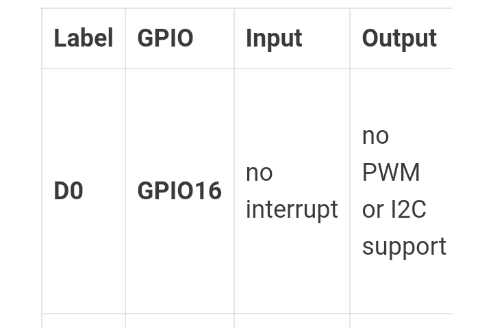
pinMode(D0, INPUT_PULLDOWN_16); // this is the pin that reads if machine is running. 15 feet away from module
Serial.begin(115200);
sensorsA.begin();
sensorsB.begin();
Blynk.begin(auth, ssid, pass );
timer.setInterval(1000L, sendTemps);
timer.setInterval(1000L, sendalert);
timer.setInterval(1000L, state);
}
void sendTemps()
{
sensorsA.requestTemperatures();
sensorsB.requestTemperatures();
temp1 = sensorsA.getTempFByIndex(0);
temp2 = sensorsB.getTempFByIndex(0);
Serial.println(temp1);
Serial.println(temp2);
Blynk.virtualWrite(V1, temp1);
Blynk.virtualWrite(V2, temp2);
lcd.setCursor(0, 0);
lcd.print("Dirty ");
lcd.print(temp1);
lcd.print(( char)223);
lcd.print("F");
lcd.setCursor(0, 1 );
lcd.print("Clean ");
lcd.print(temp2);
lcd.print(( char)223);
lcd.print("F");
}
void sendalert()
{
if (digitalRead(D0) == HIGH && temp1 < 120)
{
Blynk.logEvent("low_temp", String("Water Temperature Under Threshold Tº: ") + temp1);
Serial.println("alarm");
}
}
void state()
{
if (digitalRead(D0) == HIGH)
{
Blynk.logEvent("washer_runtime");
Blynk.virtualWrite(V0, HIGH);// this keeps track of when the machine is running
}
else if (digitalRead(D0) == LOW) {
Blynk.virtualWrite(V0, LOW);
}
}
void loop()
{
Blynk.run();
timer.run();
}
```cpp
Remove some of the changes, and eliminate some of the questionable things you’ve done until you get to a point where it’s working again.
Of course, it’s possible that you’ve killed your NodeMCU worth the excessive current draw, or mis-wiring the display or relay (which doesn’t seem to be mentioned in your sketch).
Reverting to a last known working situation will help you eliminate that possibility.
System works now, as long as I dont use the external hardware to process the signal. ( taking the 24 v and send it to NodeMCU Pin. I will try using a different GPIO and see.
What the “no interupt” portion would mean? I am not, by any means, an expert. The reason I used such pin is because it has a pulldonw resistor and that way it was easy for me to set it up to get a 3,3 V signal to make it high. The rest of the pins have pullup resistors and I am not sure if I can make them work the same way.
I hope my explanation can give you some insight, I am very thankful for your responses
It means that if you use the attachInterrupt command it wont work with that pin.
GPIO0 isn’t a good pin to use, you’d be better using a 10k pull-down resistor on a different pin, or pulling the pin LOW with a digitalWrite command.
talk of 24 volts on NodeMCU pins that can only tolerate 5v is a bur worrying, but you don’t seem to want to share the “big picture” so it’s difficult to know what thi9s really means, That’s why I’d said that it’s you that needs to do the fault finding in a systematic way.
I am sorry, I am using a 24 volt to 3.3 volt optocoupler to convert the signal from PLC to NodeMCU. The optocupler is powered by a separate power supply and both grounds ( the opto’s and NodeMCU’s ) are bonded so the output from the optocoupler is the input for the NodeMCU pin.
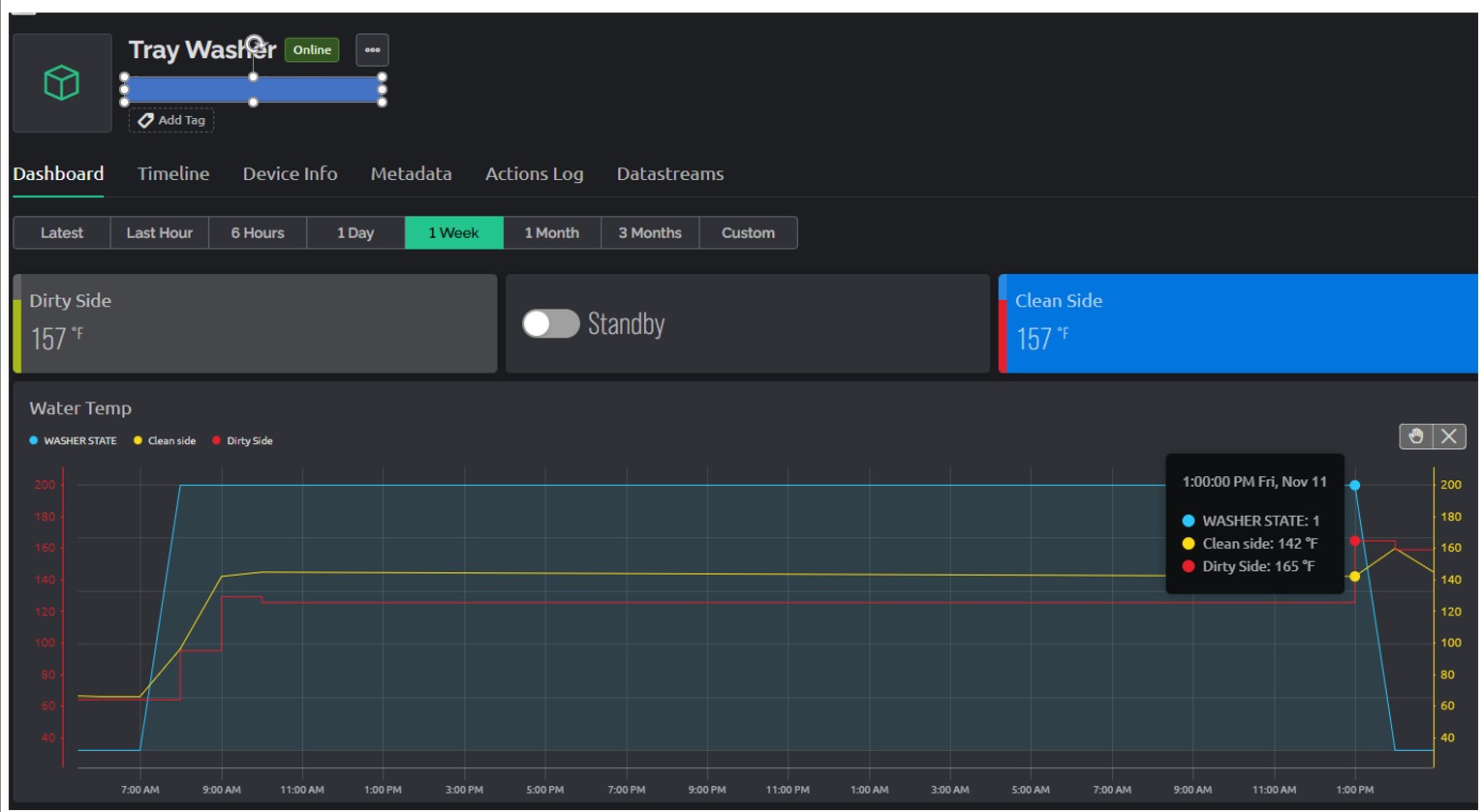
Thanks to everyone for your help, I have changed the code to use D5 as input pin, also moved the optocoupler closer to the NodeMCU module. Below is the updated code. Also a Screen shot of what the dashboard looks like so you can have a better understanding of what the system does. There is a machine that washes plastic trays. The process requires water to be above 120 degrees, there is , a dirty side and a clean side, where water is heated on two separated steel tubs ( 320 gallon each) and we want to track the temperature when the washer is running. There is 5 25 HP pumps controlled by a PLC to spray and wash down the trays, and so I use a signal from the PLC to “record” when the machine is on “RUN” state.
Pete, I had problems at the beginning when I first used events and notifications but I thought I worked out all my issues with multiple events being sent by using the timers
That was very informative, I believe I’ll thinker with it on a home project to gain some experience. On my current application is not as problematic since the “run state” is only true one or two hours a day, maybe four on a particularly busy day. Thank you both for your support