Reading Battery Voltage on AO

Hi guys.

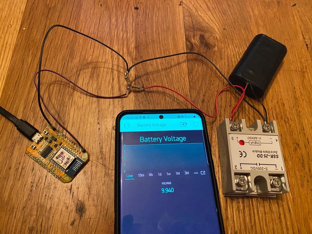
I’m somewhat perplexed as to why I’m unable to get a stable and accurate voltage reading. I suspect its my voltage divider, resistance is too high. I chose 64k resistors to reduce power consumption and hopefully to protect the microcontroller from the 50V+ it will be connected to if I can get it working.
The SSR is just a load to drain down the two 18650 cells. I was hoping to see the voltage slowly drop but somethings wrong. It is dropping but the reading is too high. The voltage should read about 8V.

And here’s the code:

#define BLYNK_PRINT Serial
#include <ESP8266WiFi.h>
#include <BlynkSimpleEsp8266.h>

char ssid[] = "**********";
char pass[] = "**********";
char auth[] = "**********";

int value = 0;

float voltage;
float R1 = 64000.0;
float R2 = 64000.0;

BlynkTimer timer;

void myTimerEvent()
{
  value = analogRead(A0);
  voltage = value * (4.970/1024)*((R1 + R2)/R2);
  
  Blynk.virtualWrite(V5, voltage);
}

void setup()
{
  // Debug console
  Serial.begin(9600);

  Blynk.begin(auth, ssid, pass);

  timer.setInterval(1000L, myTimerEvent);
}

void loop()
{
  Blynk.run();
  timer.run(); // Initiates BlynkTimer
}

Do I have the ADC voltage wrong?
Is it my Voltage divider?

Any idea’s anyone?

I think my voltage divider is working.

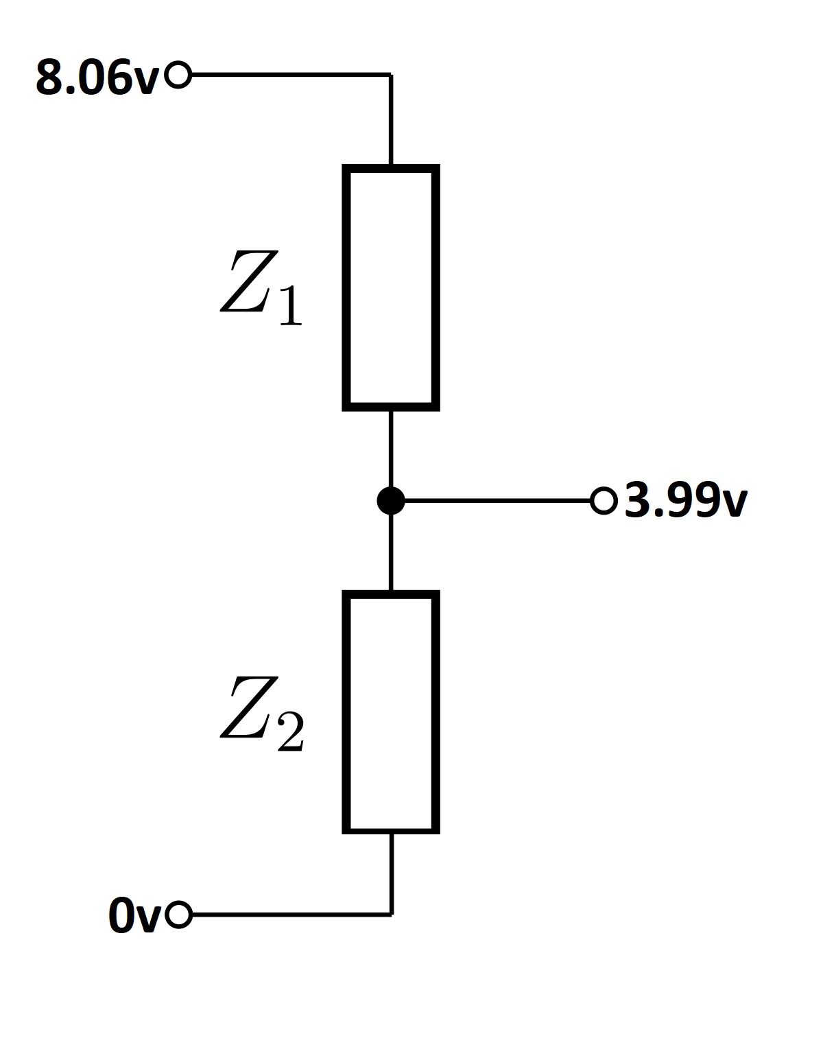
Disconnected from the microcontroller these are the voltages I get.
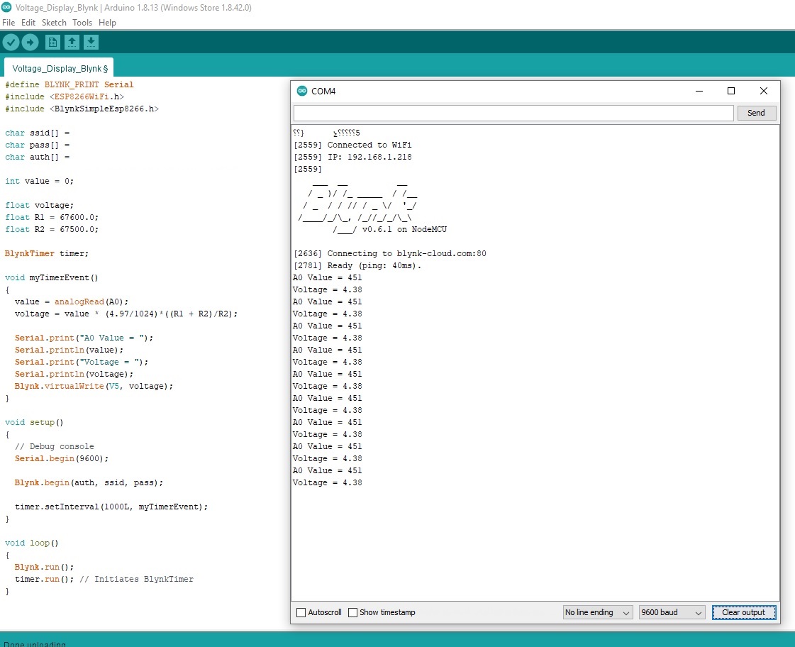
I connected a brand new AAA Duracell battery to it(1.6v). I got 2.281v returned via Blynk… :exploding_head:

I think a voltage of 3.3v applied to A0 is what is required to give the maximum reading of 1023.
So, applying 3.99v will be (slightly) swamping the input and result in a constant maximum reading.

It’s actually slightly confusing when you read some of the ESP8266 documentation, because the bare chip only enquires 1v to gove the maximum reading, but NodeMCUs etc have an onboard voltage divider which extends the 0-1v range to 0-3.3v range.

Pete.

1 Like

So why does it still fail when I use a AAA battery?

1.59v before the voltage divider and 0.79v after the divider. So only 0.79v on the A0 pin … :frowning:

What happens is you serial print the actual analogRead(A0) value before you do the maths on the result?

Pete.

1 Like

Damn! I was sure the code was correct… :shushing_face:

Oh dear, now I think my maths may be at fault … :woozy_face:

Where does the 4.97 in your equation come from? Seems a bit random to me.

Pete.

I was expecting the ADC voltage to be the same as the board voltage(5v). To be sure I got my old Fluke meter out and measured it.

No, the ADC is like the other pins, 3.3v

Pete.

1 Like

Oh, so that should be a lot nearer 3.3v :crossed_fingers:

Changed it to 3.45v and it gives me a pretty accurate reading now as long as the voltage I’m measuring isn’t above 6v. Is that because of the 3v limit on the A0 pin?
So for higher voltages(50v+) I’m going to need a much better voltage divider, one with multiple resistors as the one I’m using now only halves the voltage?

As I said earlier. 3.3v on the pin gives maximum ‘deflection’ of 1023.
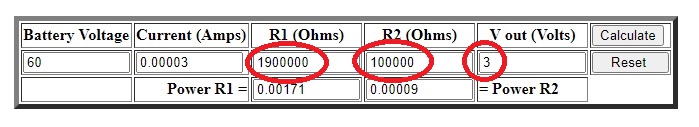
If you calculated the voltage divider so that your nominal 50v input give a 50% ‘deflection’ then 512 would be the corresponding reading.
Meaning that you’d be getting roughly 0.1v resolution.

If you sized your voltage divider so that 50v gives an output of 1000 on the sale of 0-1023 then the resolution would be 0.05v, but you’d only have a 1.15v margin at the top end, so 51.15v would give you maximum ‘deflection’ with a maxed-out reading of 1023.

Pete.

1 Like

Could a pentiometer be used as a voltage divider?
Give me an easy way of calibrating the whole thing for high and low voltages ?
I have a couple somewhere, I guess I could just try it … :stuck_out_tongue_winking_eye:

EDIT.
No, same problem…

Yes, potentially :smiley:
But, TBH you are better-off using high tolerance fixed value resistors to give the maximum stability.

If you want to measure two different voltages using the same device then you’re probably better using an ESP32 which has multiple pins that can be used as analog inputs. A couple of things to watch out for though, some of those pins can’t be used the same time as WiFi (those in the ADV2 group), and the default is that you’ll get 4095 as the maximum output for a 3.3v input.

Pete.

1 Like

Damn those resistors!

Well, I think I have the solution, thanks to a little online calculator I found… :stuck_out_tongue_winking_eye:

Hmmm, not sure about 1.9 Meg as a suitable R1 value.

Pete.

Finding a 1.9Meg is difficult so I’m thinking two 1.0Meg is close enough as I can get my hands on those easier?

Ok, I’m convinced my code and maths are good.
Its just my voltage divider that sucks.
Works well for <6.3v but is useless for >6.3v

#define BLYNK_PRINT Serial
#include <ESP8266WiFi.h>
#include <BlynkSimpleEsp8266.h>

char ssid[] = "*************";
char pass[] = "*************";
char auth[] = "*************";

int value = 0;
float voltage;
float R1 = 67600.0;
float R2 = 67500.0;

BlynkTimer timer;

void myTimerEvent()
{
  voltage = value * (3.3 / 1024)*((R1 + R2)/R2);
  value = analogRead(A0);
  
  Serial.print("A0 Value = ");
  Serial.println(value);

  Serial.print("Voltage = ");
  Serial.println(voltage);
  
  Blynk.virtualWrite(V5, voltage);
}

void setup()
{
  // Debug console
  Serial.begin(9600);
  Blynk.begin(auth, ssid, pass);
  timer.setInterval(1000L, myTimerEvent);
}

void loop()
{
  Blynk.run();
  timer.run(); // Initiates BlynkTimer
}

So, I can save this as a “good” working code and start working on how to integrate it into my EPever Controllers & Blynk code …

Feel free to tell me my code is “pants”. But if you do please tell me why so I can try and fix it, because I think its great … :stuck_out_tongue_winking_eye:

You’re calculating your result before you’re taking your reading!

I think your choice of resistor values look far too high to me. I’d be expecting values in maybe the 50k - 200k range.

Pete.

1 Like