Yes. I’ve been here before, and I’m delighted to say I actually managed to complete a few projects. But, after spending the last few years on site out in the elements. The wind, sun and rain has washed out all traces of my ability to code, not that I had much in the first place.
So, here is my attempt at reading the data from my solar controllers and displaying it on my phone using Blynk…
I saw this:
The guy connects his Pi directly to the controllers RS-485 port utilising TX and RX.
First question, is this possible with a Wemos D1 Mini? Can it be directly connected to the controllers RS-485 port utilising TX and RX?
The Pi tutorial is for controllers that use serial rather than RS-485, so won’t work with at least the two leftmost controllers in your setup. I’m not sure about the on on the right, what’s it’s model number?
RS-485 To serial controllers are easy to get hold of and are very cheap, so you can use those with a NodeMCU/Wemos D1 Mini quite easily.
The biggest issue is that the output of the RS-485/serial converter needs to connect to the serial port on the Wemos (unless you use SoftwareSerial, and I’m not a fan of that approach).
This means that debugging is more difficult, but you can use the Serial1 port on the Wemos (which is Tx only) and an FTDI adapter for debugging.
The other issue is that wiring-up an RJ45 connector isn’t very easy, because many network cables use aluminium wires so can’t be soldered onto a strip board.
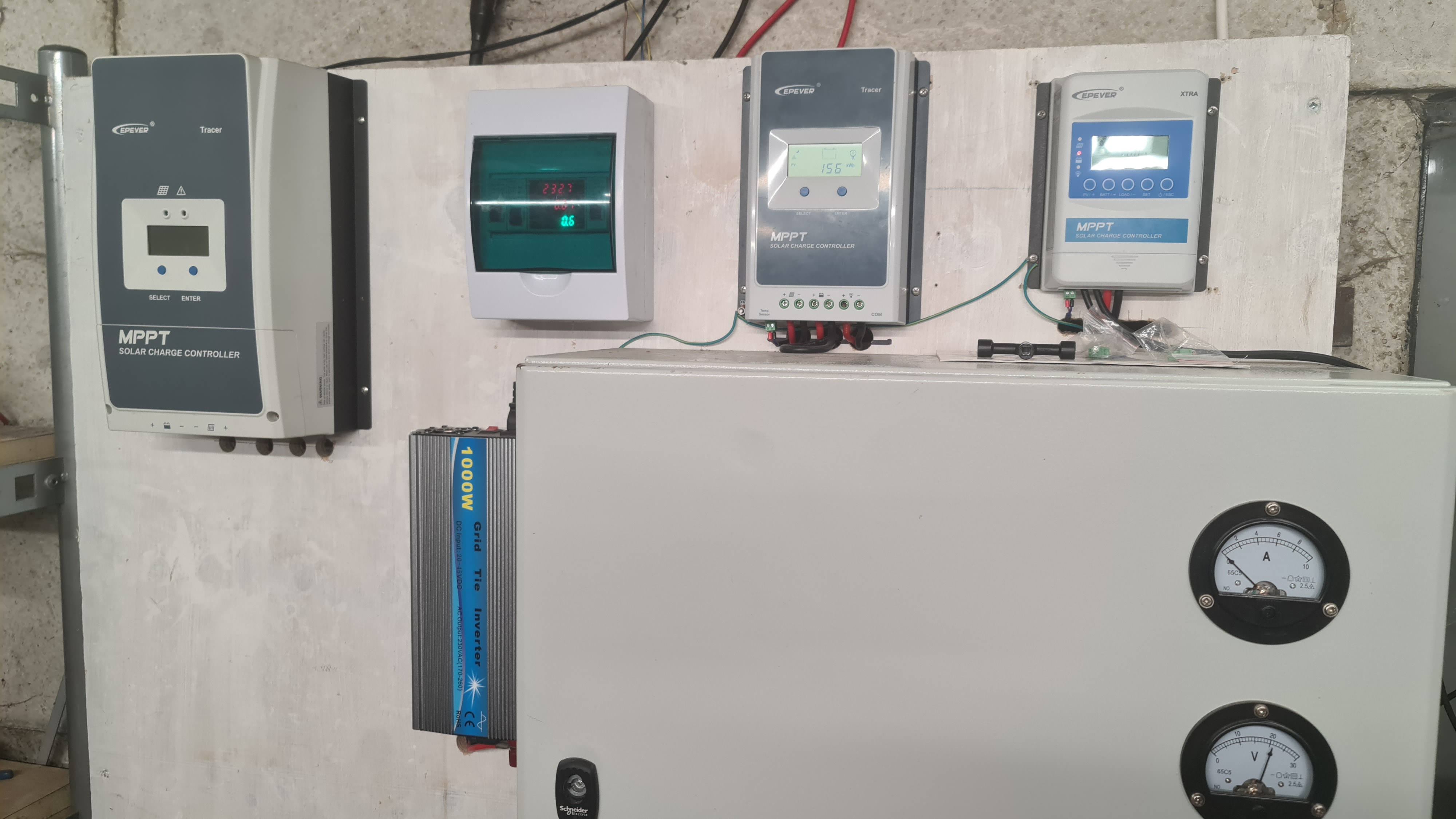
Its an EPever XTRA 1206N, one of their newer designs. It has two 150w solar panels connected to it charging 24v lithium batteries in the grey cabinet. Batteries in the cabinet are also connected to a 400w wind turbine via the gauges(bottom right of the pic). MY WIND TURBINE
“SoftwareSerial”, not a fan, why?
However, it is possible via SoftwareSerial and no other hardware required?
I’d not soldering them, I’d just use jumper wires onto the pins.
SoftwareSerial for Arduino doesn’t work correctly on the ESP8266. There is an ESP8266 version…
but I have to say that I’ve never tried it.
I’d much rather use a hardware serial port than emulate on in software, and as the Wemos has one and a half then that’s a simpler solution as far as I’m concerned. Hooking-up a serial monitor is only needed for development and debugging anyway and I have lots of FTDI adapters kicking around so its a no-brainer for me.
Maybe I didn’t explain properly.
I initially started with an old network cable and cut one end off. The ‘good’ end plugged into the controller and the other end was used to connect to a stripboard that carried my RS-485 to serial adapter, the Wemos and a 12v to 5v buck converter. Connecting the hacked-off end of the cable into this board always felt like a bodge, especially when it needs to go via a crimp connector as you cant solder the wires easily (some RJ45 patch cables do use wire that can be soldered, but its a bit of trial and error).
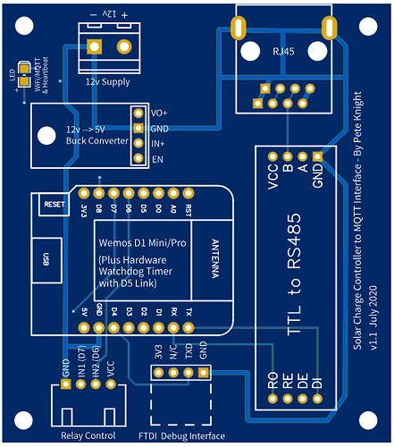
My preference was to use an RJ45 socket on my circuit board, but the pin pitch isn’t suitable for 0,1" pitch strip boards. That’s why |I went for a custom circuit board…
The other option is to use an ESP32, with three hardware serial ports. I guess you also need to decide if you want three monitors, or to try monitoring all three Tracer units with one device (could be tricky, but I guess it might be do-able.
And the party begins.
The ESP8266 version will be my choice, thank you.
Erm? You have your OWN custom circuit board ? ?
And I can buy one from ?
Yep, that’s my plan, all three on 1 device. The PC software lets me give each controller its own ID so I’m guessing I might be able to do the same thing.
So an ESP32 could be a better option for connecting to multiple controllers?
There will be at least 3 more in the future.
Well, I’m slowly getting somewhere. After hours of searching the internet I found some very helpful code. Just waiting on hardware, ordered a MAX485 “doodar” a few minutes ago and huge thank you to @PeteKnight for sending me one of his custom PCB’s.
I’m trying to figure out what the MAX485(doodar) does and why.
My understanding so far is:
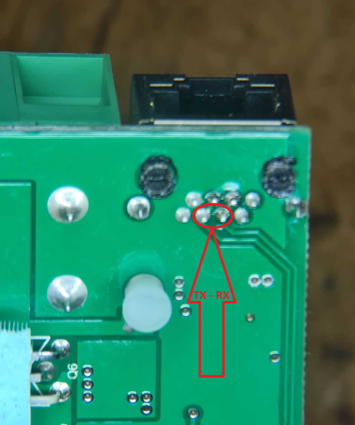
Tracer/Xtra controllers communicate over serial(TX/RX), basically 2 wires and ground. The pic below shows the rear of the RS485 socket of an EPever 20A Tracer 2206AN
My D1 Mini Pro isn’t able to communicate directly over serial so an interface of some sort is needed. Say hello to the MAX485(doodar).
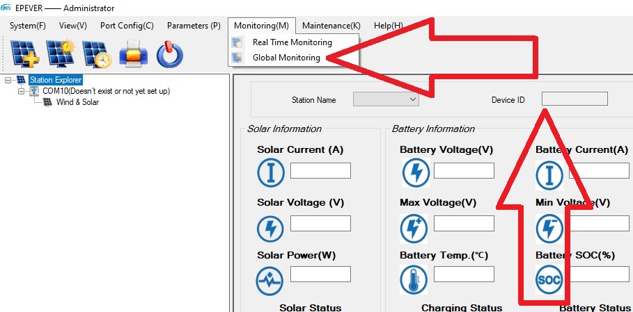
As far as I can tell, the controllers I have are “half duplexed”. Meaning data can either be sent or received, not both at the same time. The RS485 ports of my 3 controllers were linked in parallel and connected directly to my laptop via EPever’s USB to RS485 cable. I was able to give each controller its own device ID and acquire data from them via the PC software individually or all 3 using the “Global Monitoring” option.
So my next question is:
Does each controller require its own “doodar” or is there a way to use just 1 by setting device ID’s like the original software?
They actually communicate over ModBus protocol, which is RS485.
Serial ports communicate using TTL and the “doodar” converts RS485 to TTL so that it can communicate with the serial port(s) on a Wemos or similar.
I think that’s correct, but I haven’t studied the ModBus protocol. The serial port of a Wemos can also only handle either Tx or Rx at any one time, so the sketch and/or ModBus library has to manage this.
The Modbus library that I use allows you to specify which device ID you want to use to send-=out a data request then listen for the result. In the sketch that I PM’d you I speculated about how the code might be enhanced to read multiple device IDs. As I don’t have multiple devices to test it on I can’t prove if this approach will work, but I don’t see why one controller can’t interrogate multiple ID’s on the same bus (although this would need to be a sequential thing - query device 1, then device 2, then device 3).
As your devices all charge the same batteries, then you’d only need to query battery stats with one device. The other devices would presumably just be queried for solar panel output and maybe internal temperature readings.
So, I close then?
OK so I understand that now, thanks.
That’s the answer I was looking for. Now I know in which direction I’m heading.
I do, be happy to test for you once everything is reinstalled.
Ah… The 2 small controllers(centre and right) are 24v and fed power to a 24v lithium battery bank in the metal cabinet. Any surplus power is dumped into 48v lead acid batteries via a large 1500w buck booster. The large controller on the left is 60A 48v that feeds the large bank of lead acid batteries. All 3 controllers and the wind turbine share a common ground. And I suspect all 3 RS485 sockets use the same voltage. I wasn’t expecting this to be a problem as the PC software handled it OK. Is it a problem?
I don’t think so.
If it’s possible to interrogate each controller in turn then you can decide what data you want from each one.
The process of requesting and getting the data from the various registers (memory locations) within each controller can be a bit slow, so it’s best to only ask for what you need, rather than requesting every available parameter.
It also gives a lot of data to upload to Blynk, and making sense of that data in a useable format in the app can also be a bit tricky, so probably best to think about your key metrics that will come from each controller and how you’ll utilise that data in the app.
I’ll be wanting it all, everything each controller has to offer.
I’ll be making my own Blynk server again, and like the original PC software I want to pull everything when accessing a single controller, but only specific data when accessing all controllers(globally).
I know this isn’t going to be easy but I’m up for the challenge.
I don’t think there’s such a thing as retrieving global data, it’s all specific to an individual controller.
If you have two controllers connected to one bank of batteries then they will (should) return the same data about battery voltage, state of charge, temperature etc., so extracting this twice may be a waste of effort.
Also, the controllers give data on the load voltage and current, but only of this is drawn via the load terminals of the controller. With your setup I don’t think yore doing this, so that data will be zero for each controller, so not worth extracting.
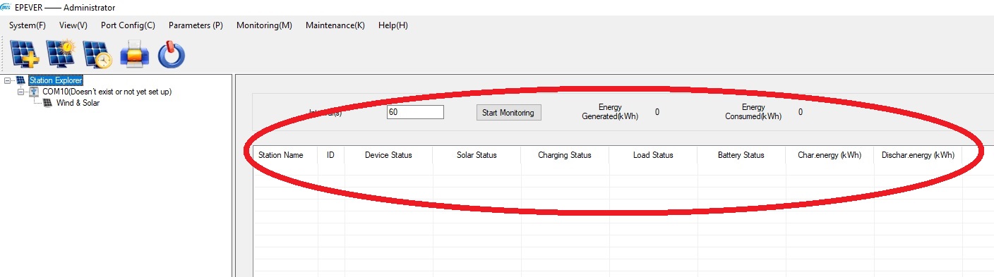
The original EPever software has a “global” option, see the pic above and the one below. It accesses each controller 1 at a time and displays just a few specific bits of data, battery status, load status, device name, ID etc.
Yes 2 controllers but supplying power from very different sources so very different data returned.
The smallest controller on the far right has 300w on solar panels. The centre controller has a used oil burning single cylinder diesel engine connected to it via a motor/generator.
The load outputs of the 2 smaller controllers are connected to the 1500w buck booster. Yes there are losses incurred in the booster but it does give me accurate data of what’s being pulled out of the lithium battery bank. I hope to add the values of both outputs in Blynk to give me the total of both.
So, as you said, that’s controller specific data, displayed as a ‘global’ summary.
This is why I was saying that you’d need to give some thought to how you display the data in a meaningful way in Blynk.
But I was referring to the shared battery bank that they supply. The inputs stats will be different, but the battery specific data should be identical - so no need to gather it twice.
Okay, I hadn’t realised that from your diagram. In that case the load data from these two controllers will be useful.
“Meaningful” to me means everything a specific controller has to offer.
I explain why below.
When I access a specific controller ID I want to see every bit of data it has to offer, even if its connected to the same lithium battery bank as another controller. Only the voltage of that battery bank will be the same(hopefully). I understand for most people what your saying is correct. But for my specific application, temperature will be specific to where the individual controller temperature probes are positioned. Giving me a better view of the overall battery temperature as its almost 2 feet wide, has hundreds of individual lithium cells in columns.
For me personally, all the data will be relevant. But I do understand, for most, it would be silly to access the same data twice. Perhaps I should have been more descriptive in my solar setups and what I personally want to achieve…
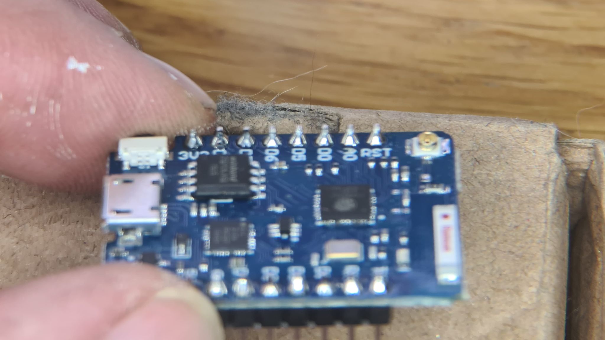
On the plus side, considering I’m 54 and virtually blind(exaggeration). I did a pretty good job soldering the pins to that D1 Mini Pro…
Specsavers is always a good option!
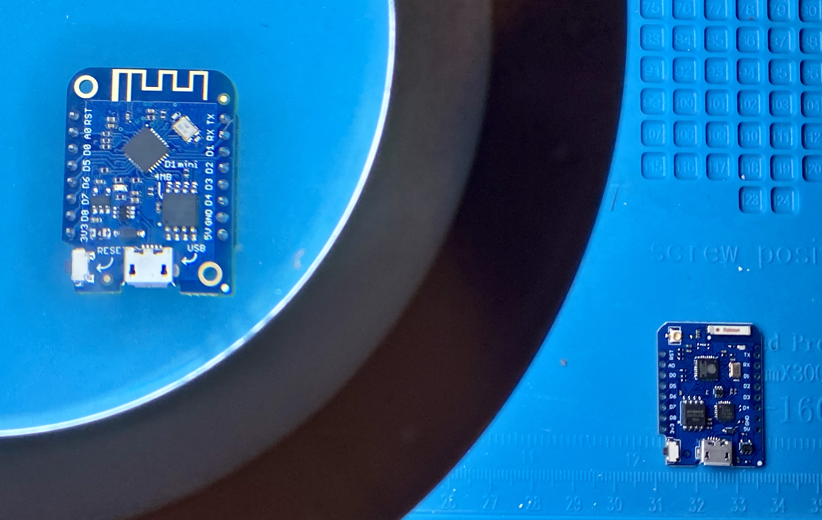
Personally, I wear varifocals but still struggle to see enough detail for soldering, especially when it comes to SMD components. My illuminated magnifier (courtesy of Maplins closing-down sale a few years ago) is a lifesaver for me.
Here’s a comparison of a D1Mini under the magnifier compared to one that’s not…
Do you get a decent WiFi signal in the place where you have your controllers, or are you planning on using an external antenna on the D1 Mini Pro?
If you are then you need to turn the zero ohm resistor that’s between the antenna connector and the ceramic antenna through 90° (anti-clockwise), which should be fun!
I’ve not needed glasses before, things on site tend to be large and 30 ton+ so you can feel them coming long before you see them…
The site drawings are digital these days so just pinch to zoom.
But these little microprocessors are something else. Time to get another illuminated magnifier I think, what a huge difference they make.
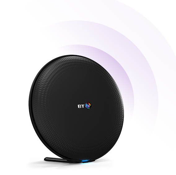
I have BT Complete WiFi at home, they gave me a couple of these things.
A lot depends on the quality of the antenna that you fit. Many of the cheap Chinese ‘rubber duck’ ones that you see on eBay aren’t really that great, but may give 3db increase in signal strength, which is effectively double, so worth doing if the RSSI is marginal.
I use one in my shed in Spain, and it helps quite a bit. I also have a Wemos in a metal box that’s part of my door entry system, and I need one on that otherwise the Wemos is completely shielded.
The BT mesh system looks quite good, apart from the fact that it’s BT, so you should be fine sticking with the onboard ceramic antenna.