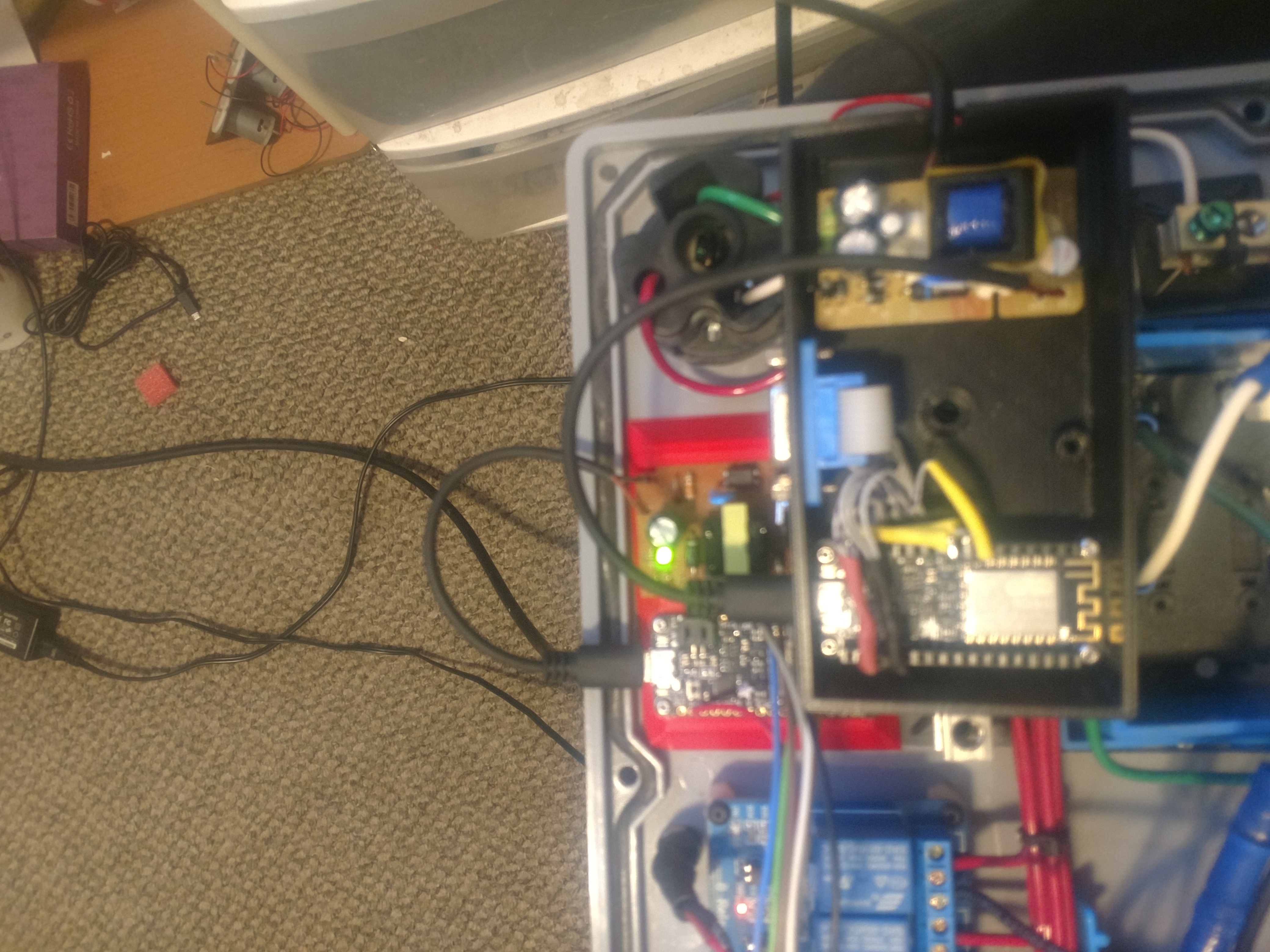
Not VGA, but DB9 which is same/similar. Prior to getting into ESP, I was developing my project around the Arduino Mega and housed the Mega in a small case. From the case, I used DB9 ports to connect with my hardware which at the time were the 8 channel relay module (pictured above), two DHT temp/humidity sensors and 8 peristaltic dosing pumps that were driven by TIP120 transistors. I’m currently in the process of migrating everything to an ESP atmosphere. The small module in the above pic is my master ESP and it will interface all of my widgets as well as run the 2 DHT22 sensors. I soldered all the GNDs and 3V leads together and also solder on right angle male header pins, Once I completely iron out the circuit configurations, I will likely remove the pin headers from the ESP and solder the wires directly.
Looks like he is using a 9-pin D-Sub plug for power and data cable connection… probably to the relay box, althogh I cannot see the matching socket on it.
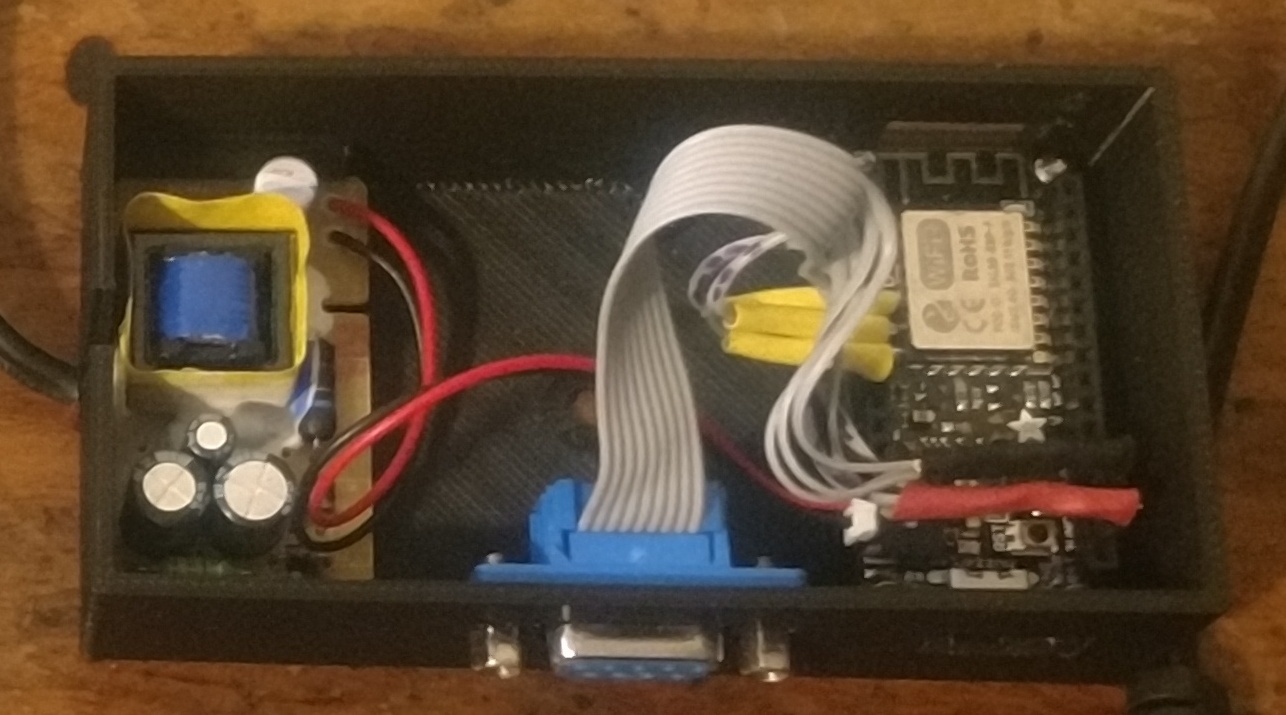
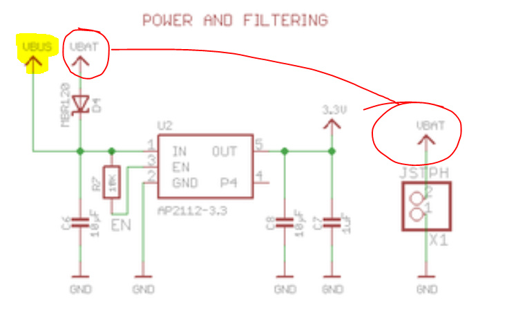
@Skybound It appears you are inputting AC converted power to the battery socket… which I hope you understand is not rated for 5v (meant to charge and feed from the LiPo, thus 3-4.2v would be my guess)… and if like any battery capable ESP I have used, will not pass or boost 5v onto the 5v pin that you have on your D-Sub, so not understanding what you are doing there.
The module next to the ESP is a 5V1A phone charger I hacked apart, put a short length of 110VAC cable on one end, and the battery JST connector on the other. I read as deeply as I could into the Adafruit datasheet for the Huzzah Feather and was lead to believe that everything more or less ties together inside, so I chose to go this route to power the ESP. Assuming I didn’t already smoke the board from powering it the wrong way or over driving the pins, how would you suggest I inlet the 5V supply? If I did smoke it, I have others.
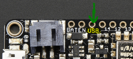
Through the USB pin just like if it was from a USB plug.
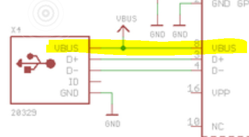
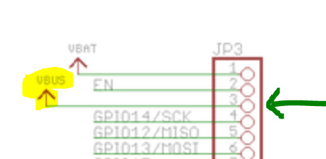
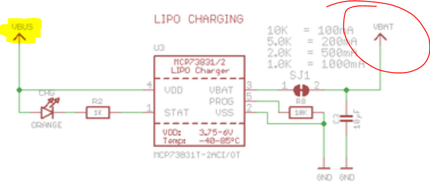
But not through the battery connector (VBAT)… the SCHOTTKY BARRIER RECTIFIER is probably limiting the voltage.
Ok, I replaced the liPoly JST connects with micro USB on both boards as pictured below.
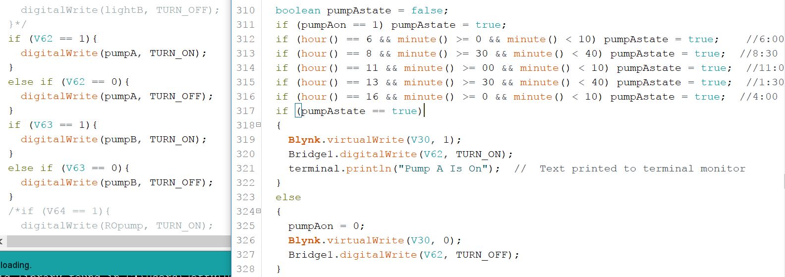
Also, please look at the side by side of the sketches. The left is the slave with relays connected to each pin. I’ve commented out 5 of the 8 relays, so only 3 can operate. 1 of those 3 channels already performs great. So I’m now just trying to verify if my code looks good/functional for the other 2 channels. The code snippet is only for one of those channels, but the other is identical.
left side is the slave and right side is the master. Also, is pasted the handlers that are in both sketches. What I want is to press a button in my app (pumpAon on V30) “or” if the time makes the function true, send the value of 1 (TURN_ON) over the bridge on V62. The slave should see the value on V62 and execute digitalWrite commands based upon what value V62 holds.
BLYNK_WRITE(V62) {
  CC = param.asInt();  // pumpA remote
}
Does the above look correct? Below is my USB power feed from the respective hacked phone chargers.
So if I understand you want to send data to a selected bridge.
Here is what I did.
I created 3 devices with the same code each having a seperate id.
I then create three bridges in each device so that they can talk.
like this
#define bridgedata      V9

WidgetBridge bridge1(51);
WidgetBridge bridge2(52);
WidgetBridge bridge3(53);

BLYNK_CONNECTED() {
  bridge1.setAuthToken(a_token);
  bridge2.setAuthToken(b_token);
  bridge3.setAuthToken(c_token);
}
to select the device to talk to I send a message to the master device. and set a flag that tells the device that it is waiting for a message.
Like this
BLYNK_WRITE(vpin##)
{
  talktome = 1;
  bridge1.virtualWrite(Same Vpin##, 1);     //bridge 1 is the master
}
when the master get this it sends the data to the other devices like this
BLYNK_WRITE(VPIN??)
{
  bridge2.virtualWrite(bridgedata, cardHolder[0], cardId[0], accessFlags[0]);      //bridge 2 slave
  bridge3.virtualWrite(bridgedata, cardHolder[0], cardId[0], accessFlags[0]);      //Bridge 3 slave

}
you look for the data on the device like this
BLYNK_WRITE(VPin$$) // copy card to lock hardware
{
  if (talktome) {
    talktome = 0;
    cardHolder[0] = param[0].asStr();
    cardId[0] = param[1].asStr();
    accessFlags[0] = param[2].asInt();
  }
}
The talktome flag is defined as a global int.
@Gyromike Please take note of the time date stamps before revising old topics… children are conceived and bore in the time since this post… The OP probably figured out the answer in that timeframe as well 
I understand however it may help others that have a similar question
Thanks. but as I mentioned to you before, concerning old topics… please consider putting together another “Projects Made with Blynk” tutorial or something, like you did for NFC. That way we keep topics fresh without dragging on old ones for years… They can often get confusing after a few months due to constant development changes.
Thank you.